Performance Measurements of a Motorola VHF Micor
Helical Filter Modified for 220MHz

All photos clickable for a larger view.

Micor Helical
The VHF high-split Micor 5-Pole
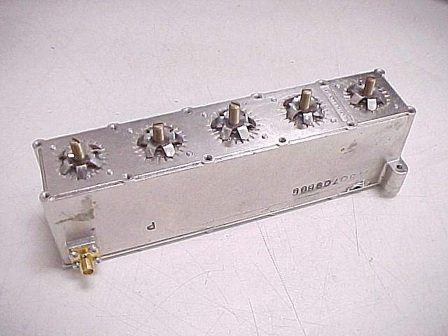
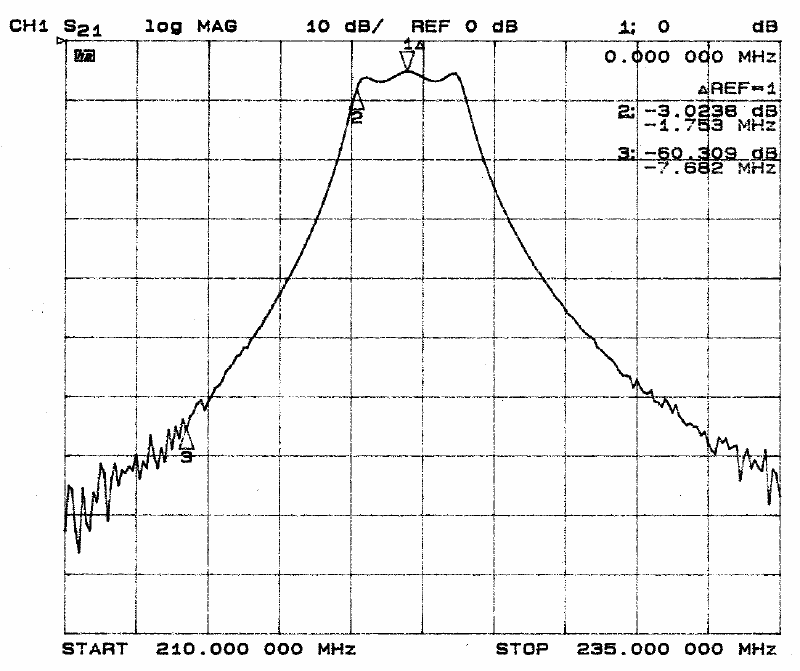
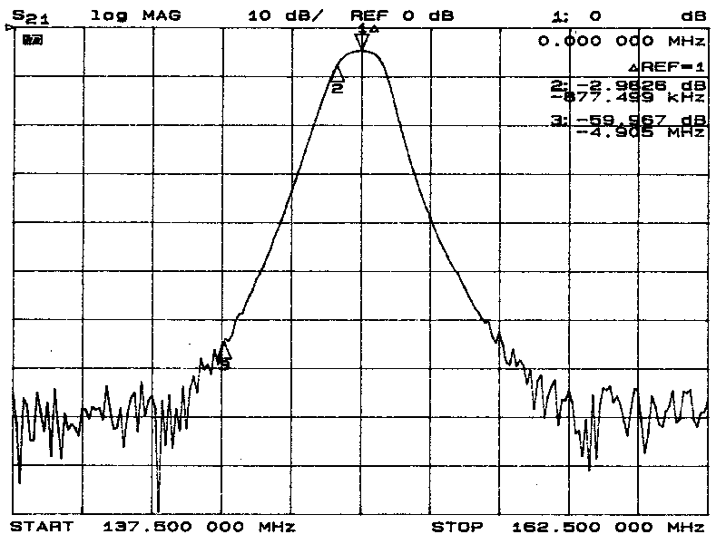
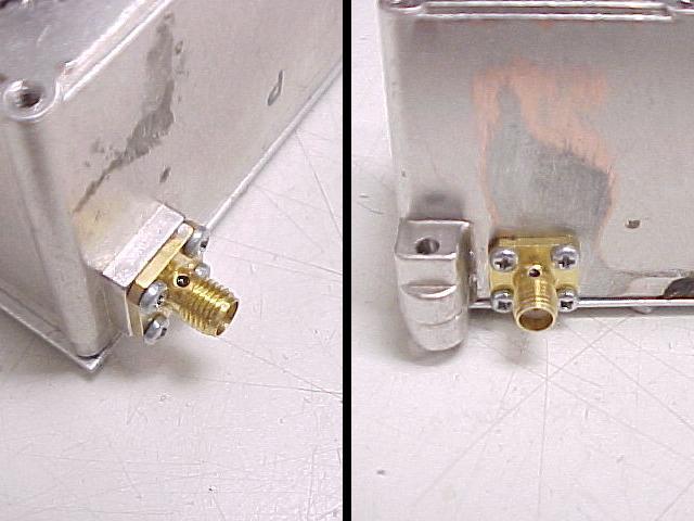
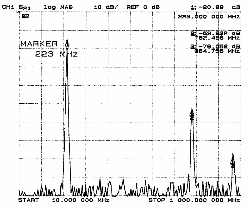
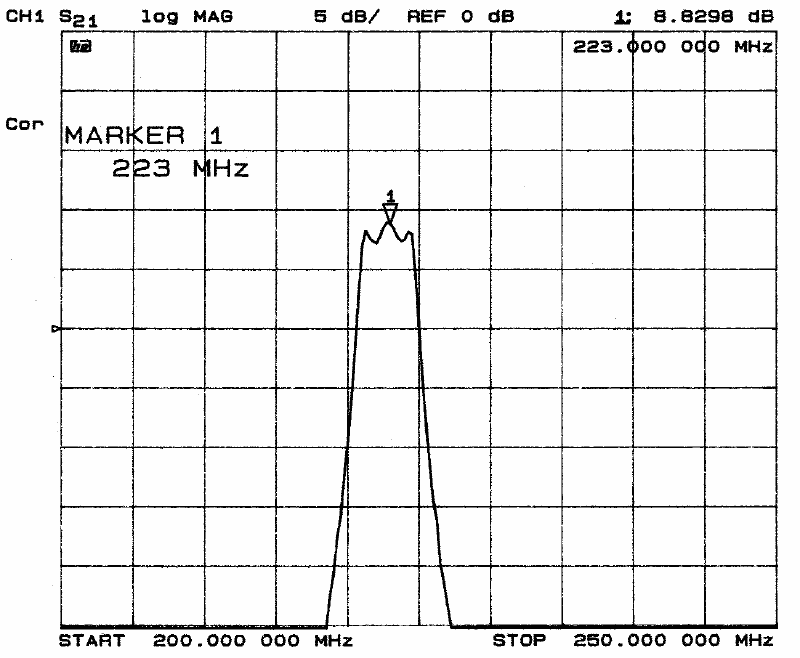
Helical Filter Modified for 220 MHz.


Introduction
This entire effort was brought about in an attempt to assist my friend Gary, KH6JTM resolve some interference issues with his 224.580 MHz repeater in NE Albuquerque. Gary built his 220MHz repeater by modifying a high split VHF Micor using instructions he found at the Repeater Builder's Technical Information website. These modifications include steps to convert the 5-pole helical filter from 160MHz to 220MHz. It "peaks up" at 220MHz, but just how well was it working compared to the stock filter, and would there be any benefit to adding a second filter ahead of the receiver? I have access to a Hewlett-Packard 8753C 6GHz network analyzer at work, so I offered to sweep the filter and test Gary's modified 220MHz preamp at the same time.

HP8753C Analyzer
Here is the HP8753C Network Analyzer used
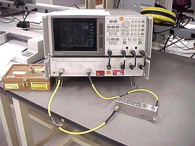
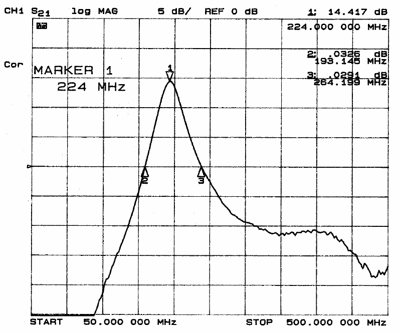
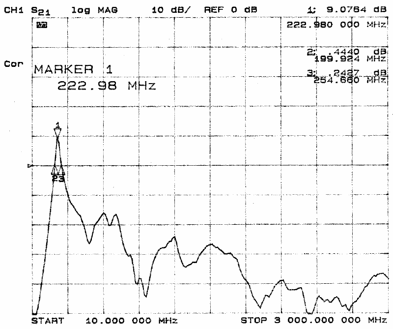
for these test measurements.


Setup/Preparation
Gary performed the initial modification per the documentation to the helical filter I tested. I modified it a bit further by replacing the phono connector at the input, and plain wire output with chassis mount SMA connectors. I also changed the output tap from about 2-1/2 turns from the bottom to 1/2 turn from the bottom, matching the tap point of the input coil. I was hoping to bring it closer to 50 ohms since this would be used in a 50ohm in/50 ohm out application. It ended up being around 100 ohms but I did not consider it worthwhile to try to get the match any better (plus it was mechanically difficult). That being done, the filter was connected to the analyzer and the following plots were created.

SMA View
Coil Tap
Photo showing the filter wth added SMA Connectors
Photo showing output resonator tap details.


Narrow Band Sweep
This plot shows the 3db bandwidth to be 3.5MHz, with 5.1dB insertion loss. The ripple is indicative of overcoupling between the poles, likely intentional on the part of Circle-M to widen the passband of the filter to operate over the stock Micor's intended bandsplit.


Helical Wideband Plot
Here's a wideband response plot. Spurious responses are far enough away and low enough not to worry about


Plot
This is Gary's modified preamp. This plot shows the gain bandwidth to be about 70 MHz, with the peak gain about 14dB at -40dBm of drive.

Plot
Out of band response is lower than I expected.


Motrac Helical Plot
Just for giggles, since the analyzer was already set up and cal'd, I hooked up an old Motrac helical filter. This one doesn't appear to be as overcoupled as the Micor. Insertion loss is about the same at 5dB.


Filter and Amp Plot
Here is the modified helical filter and preamp working together, with -40dBm of drive. Between the selectivity of the amp and filter combined, this setup might be of some worth. On the air testing will tell all.


Conclusion
The bottom line is that a modified Micor helical works just fine on 220MHz, though it is a little broad and lossy to be considered as a high-Q filter. Putting an additional one inline, while improving out of band rejection, would incur yet another 5db or so of loss in addition to the 5dB of loss through the helical already in the radio. 10dB of loss before you even get to the radio seems a bit much, and adding a preamp to that brings with it a whole new set of problems. If greater rejection than what is provided by a single 5-pole helical filter is required, a much better solution would be a resonant cavity.

Many thanks to Gary, KH6JTM for allowing me to keep his filter and preamp for a few weeks while I got around to measuring them.


Back Arrow
Back to the Main
Project Page
Home
Back to the K5LXP
Home Page
OS/2 Warp
© 2001 Pane Relief Computer Services