Icom 746Pro
No-Transmit
Repair
Information
Summary
A compilation of repair and modification notes for the
746Pro
"Sudden
Death" transmit problem.
Mark Brueggemann, K5LXP - Nov, 2004 - [email protected]
Executive Summary
Thanks to the internet and a variety of mailing
lists,
it's no secret there's a problem with the 746Pro
transceiver. My
own 746Pro
crapped
out in less than 6 months of operation, so this problem was
involuntarily
foisted upon me. Rather than go through the Icom warranty mill I
did my
own investigation into, and subsequent repairs of the
problem. Since that
time
I have discovered others who have done a similar effort and
devised
their own solutions as well. It only made sense to
incorporate
all
of
the known fixes into the radio at one time and take care of the
problem, no
matter which
specific issue is the root cause of the failure.
There are several
failure
modes
suspected as the cause of the "sudden death" 746 transmit problem.
They
are:
- ESD event
- Heat
- Input switching transient
- [Reserved] (for Future Failure Discovery)
The last one is listed
as
a bit of levity, but realistically I can't rule out any
other possible causes. If someome comes up
with
some hard data to support another yet-undiscovered problem, I'll
be
happy
to add it to the list. When a radio fails it's difficult to know
for
sure
which one of these was the root cause. The 746Pro no TX
problem
always manifests
itself
in the form of a dead IC151, a broadband medium power amplifier
IC.
Without
a sample of dead parts and subsequent detailed analysis, we may
never
know
exactly what is taking these parts out. The good news is the the
fix
for
the identifed suspected root causes is simple, inexpensive and
readily
implemented by most hams with simple tools. The group of fixes
here, implemented in my own rig, have allowed to it operate longer
than
it did with just the "protection diodes" Icom installed at the
factory.
Time will tell how robust these fixes will be, but to be sure
without
them you
stand
a very good chance of joining the "sudden TX death" club. Yes,
the problem
should be
fixed by Icom, but that's not going to happen. Rather than
complain
about
it, let's just fix it and enjoy this otherwise excellent
transceiver.
IC151
Popped, or not?
You turn on your rig one fine day, hit the PTT and no
joy.
You check the controls and no matter what you do, there's no
transmit
power at all. You get that sinking feeling in the pit of
your
stomach that you just became a member of the Sudden Death
Club.
But how do you know for sure? The test to see if your IC151
is
bad is very simple. Take the
bottom cover off of the unit, and remove the shield covering the
back
end of the RF Unit PCB. IC151 is at the back
edge of
the RF Unit PCB facing out. Connect
the rig to 12V power, turn it on and set the controls as follows:
Frequency: 3.5MHz
Mode: FM
RF Power: Max Clockwise
Using even a basic oscilliscope, set the sweep for 1uS and
amplitude
for 50mV per division. Press the [TRANSMIT] button on the
rig and
you should see about 20mV P-P of RF on pin 1 (RF In), and 145 mV
P-P of
RF on pin 5 (RF Out)
of IC151. If it's bad, you
will see little to no RF at pin 5. If you do see sufficient
RF
at this point and your 746 isn't transmitting, the problem is
elsewhere
and beyond the scope of this discussion.
Technical Data
I
spent a bit of time characterizing
the thermal characteristics of IC151 based on the the information found
on OZ2M's
746 Page. It seemed
unlikely at first that a part dissipating only a third of a watt
could overheat but after reading the component's Data
Sheet and Application Note,
you
discover that the only path for heat to exit the chip is through
it's
ground
leads. The copper pads for IC151 on the RF Unit PCB aren't
nearly
enough heatsink for this part. My subsequent bench measurements
confirm
this. So connecting a heatsink to the ground legs is the
only
effective cooling solution. Merely placing a heatsink on the
plastic package itself, while
it
wouldn't hurt, won't do any good either as the thermal resistance
from
the
die
through the plastic package is very high. OZ2M shows several examples of homebrew
heatsinks that fit over the
existing
IC151.
If you read OZ2M's page you learn
that
the IC-756Pro uses this same
RF amplifier IC as the 746Pro, and you don't hear of any of those
transceivers
having this sudden TX death problem. It turns out with the 756Pro,
power
is
turned on to the part only during transmit, while in the 746Pro
the
part
is powered up 100% of the time. The part in
the
746Pro has to dissipate
it's 300mW or so of DC bias current even during
RX/standby. Since
amateur
transmit duty cycles are so low it's no suprise that the IC in the
756Pro
isn't failing very often, if at all. There is also less
chance of
an unpowered part being damaged than a powered one. So it
seems
if you could
mimic the 756Pro switched TX VCC circuitry, you might
similarly reduce
your chances of failure in
the
746Pro as well.
There
isn't any convenient source of TX
switched 5V near IC151, but there is a source of TX switched
8V.
Using a zener diode from the 8V source provides the TX switched
VCC to
IC151 in the 746Pro.
Lastly, based on the experiments
performed by Steve, NB30 that he graciously shared with the 746
Yahoo
Group and gave me permission to quote here, shows there is some
validity to the ESD sensitivity claimed by Icom. Adding the
diodes to the HRX line (the 'protection diode fix') while a step
in the
right direction, is a poor stopgap
to mitigate this problem. ESD can contain a significant
amount of
energy, certainly more than what it would take to blow the PIN
diodes,
and the next part in line, IC151. A better solution is to
use a
choke,
which is virtually impossible to damage
with ESD. Additionally, Steve identified a potentially
damaging
transient to the input of IC151, along with a suggested fix.
The
text of his tests and conclusions can be found here:
Email and
ListServe
Discussions

|
|
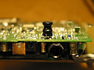
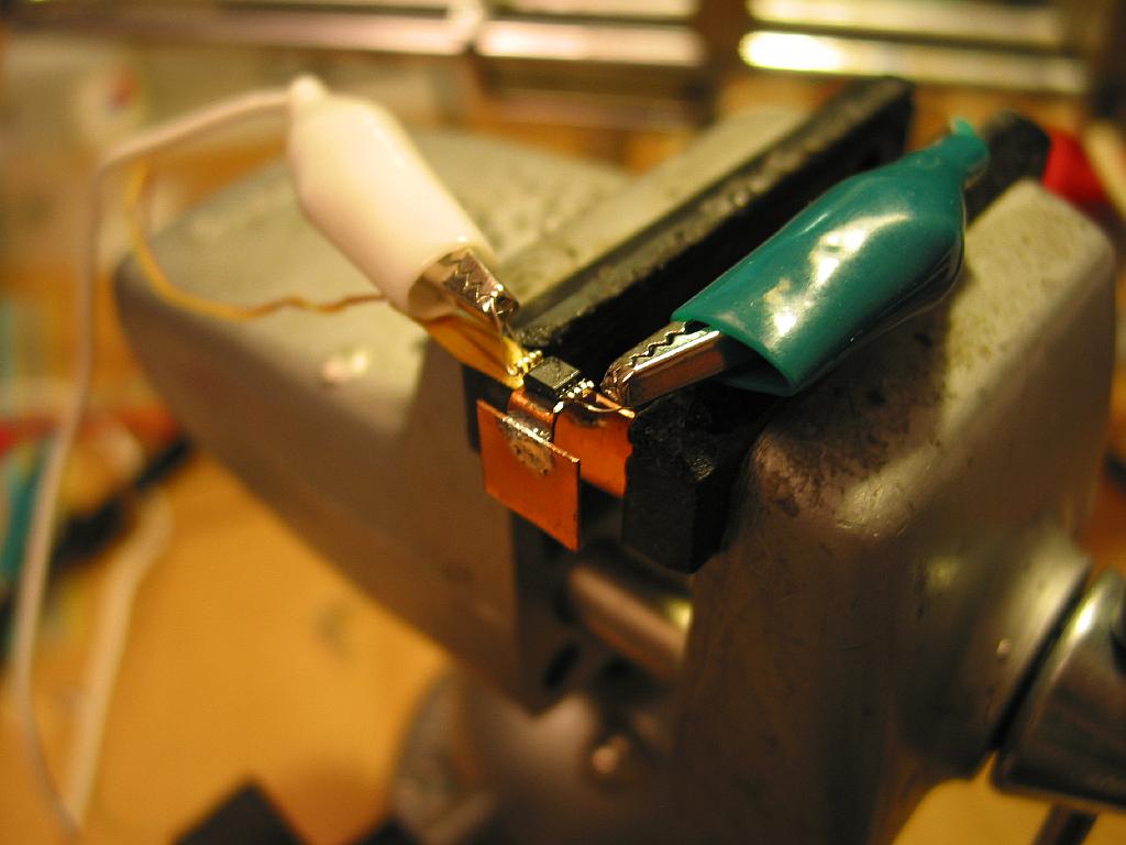
|
IC151 undergoing thermal testing using a mockup
heatsink.
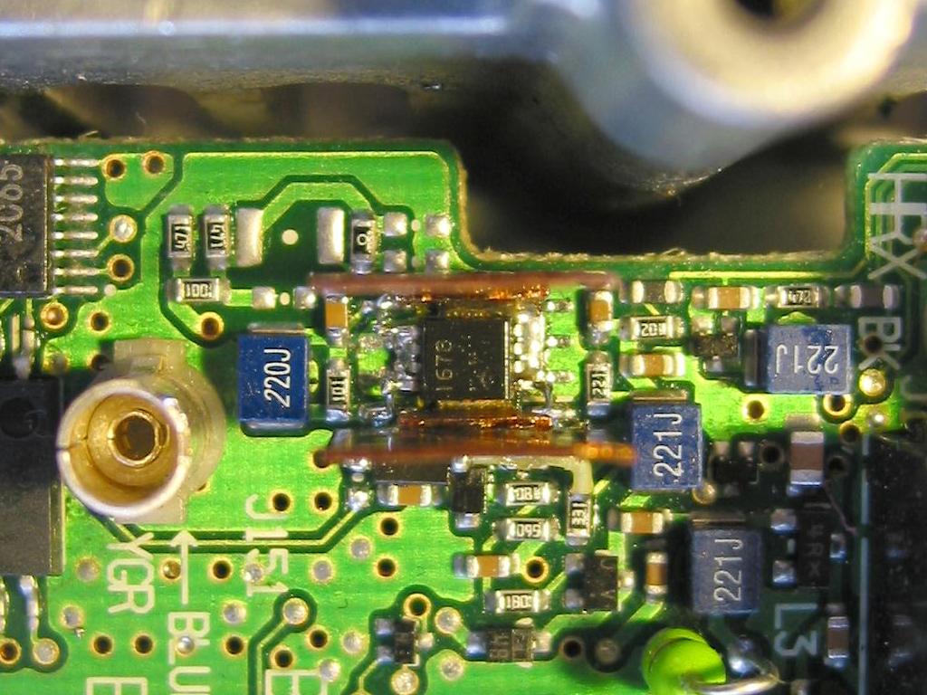
|
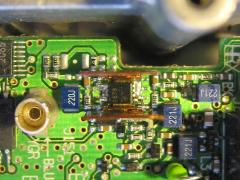
A view
of
the competed SSOIC installation on the SOIC pads, along
with the
homebrew heatsink. |
STANDARD
DISCLAIMER
If you weren't already aware that
the
746Pro is comprised mostly of
0603 (60x30mil) size surface mount parts, you're about to discover
it. While performing the fixes below are basically no more
difficult than installing the optional high stability oscillator
module, not every ham posesses the skills required to perform
them. If SMT makes you long for the days of Heathkits then
maybe
this isn't for you. If you go ahead anyway and hose it up,
don't
blame me, I'm not the one holding the iron. And no, I'm not
in
the business of fixing ham radios but I'll
gladly help folks any other way I can. The fixes described
here
worked fine on my own rig but due to circumstances beyond my
control I
cannot guarantee their efficacy in any other unit. Proceed
at
your own peril. (Scary, eh?)
What
you'll need.
You're going to need the following
parts, Digi-Key
part numbers are shown but they may be alternately sourced as
necessary.
1ea IC151 RF
Amp: Icom# 1110001890, DK#
UPG1678GVCT-ND
2ea SOT PIN Diodes:
1SV252, Icom# 91213606, Substitute- DK# BAT54SWT1OSCT-ND
1ea .01uF 0603 X7R
Cap:
DK#399-3189-1-ND
1ea 1 millihenry
molded
axial leaded
Choke: DK# TK4312-ND
1ea 2.7V Zener:
DK#
MMSZ5223BDICT-ND
The UPG1678 from Digi-Key is an SS08
package, not
an S08 as originally used in the radio. If you're careful,
you
can bend the leads out and get them to fit on the S08 pads.
Alternatively you can get the exact replacement
from Icom. If you're reading this before your radio died and
are
doing the fix as
a preventative measure, you can leave it alone.
I couldn't find a retail (or even OEM)
source for the 1SV252 diodes,
so the most
convenient source becomes Icom for those. If you don't care about
using
"genuine" Icom replacement parts, the BAT54 diodes from
Digi-Key are a form/fit/function
replacement and I think a better substitute than the
original.
While it may seem superfluous, I would order at
least two sets
of everything. This will cover at least one botched attempt
or
lost part. Having spares on hand will save you much time and
effort than
if you'd only ordered one, had a problem, and had to repeat the
order
and wait. It's only a few extra bucks.
Something you may consider doing while
having your 746Pro on the operating table is to install the CR-282
High
Stability Oscillator module. If you operate much on 2 or 6M
weak
signal modes, the 7ppm frequency (in)stability of the 746Pro is
pretty
noticeable. You'll have the radio apart to that point
anyway, and
you can fix
two problems at once (drift and sudden TX death). Just a
thought.
Component
Installation Details
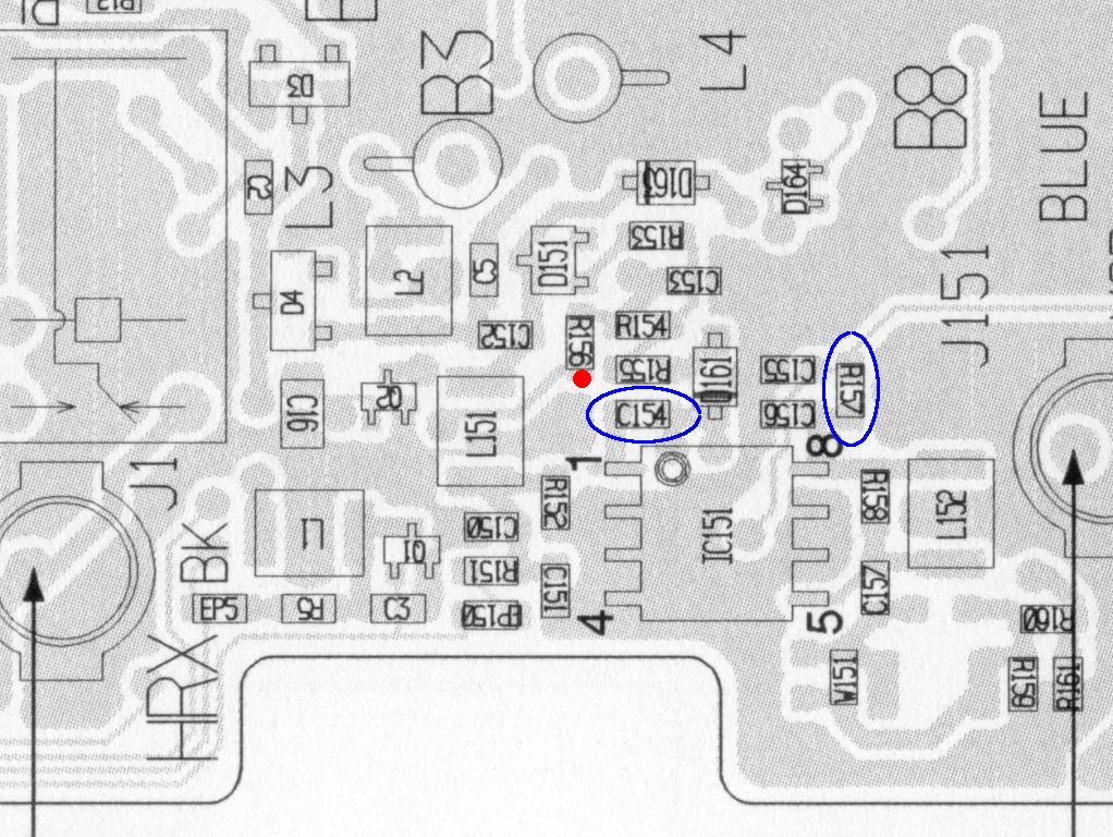
Refer to the
diagrams and photos for
placement of the new/replacement parts. Photos are clickable
for
a high
resolution view.
The 1SV252 SOT diodes are the ESD
protection
diodes. If they aren't present in your radio, it would be a
good
idea
to install them at this point. Even if your radio already
has
these installed from the
factory,
it might not be a bad idea to replace them. If your IC151
was
blown
by ESD, it's a given that one or both of the diodes are fried or
weakened
and
should be replaced. Even
though their overall effectiveness is questionable, it doesn't
hurt to
put them
in. You will have to remove the RF
Unit PCB to get to the backside of the board to install/replace
the
diodes. It will help to remove the small shield that covers
one
of them. Details on how to remove the RF Unit PCB can be
found on
page 91 in
the
746Pro Instruction Manual, in the section that describes how to
install
the high stability oscillator module.
After the diodes are in and the shield
soldered
back in place, trim the leads of the 1mH choke to about 1/8" and
solder
it
on the
bottom of the PC board connected between the pad for
the center pin of the HRX connector (J1) and the PCB
groundplane.
You will have to scrape away some solder mask on the groundplane
to
expose the copper. That should
shunt any errant DC and static that should come down the HRX pipe.
This
is
the intended function of the Icom diode fix, but a choke is a lot
less
likely to get
blown out as the diodes are. This completes work on the
bottom
side of the PCB.
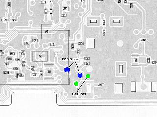
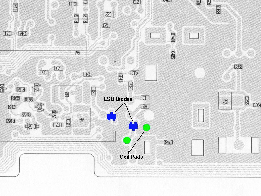
|
|
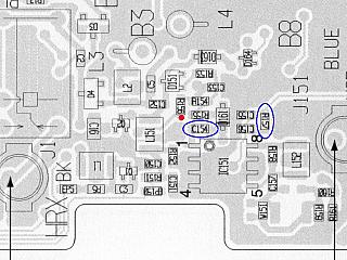
This diagram shows the location of
the "protection diodes" and the
soldering points for the choke.
|
Here is a view of the PCB with the
choke soldered in place. There is
plenty of room for the choke even
standing up like it is.
|
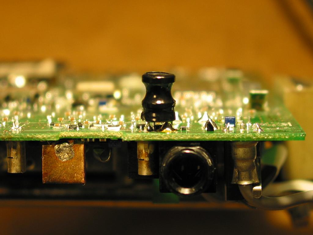
On the top side of the PCB, R&R C154 with
the .01 cap. That takes care of
the RX-TX switching transient issue.
If your IC151 is dead you will have to
remove and
replace it. If you order it from Icom you'll get an exact
form/fit/function S08
replacement. If you order it from Digi-Key or Mouser you'll get
one in
a different package, as the original SO8 version was obsoleted by
NEC/CEL some time ago.
The two
versions
are functionally and electrically interchangeable. It is
possible
to fit the SS08 version on the S08 pads, but will take some lead
bending/extending
and careful soldering. If anyone has a source for real
S08 UPG1678's other than Icom
I'd love to hear
about it. The only sources I've found are obsolete parts
brokers
that will only sell them by the reel.
You may consider adding a heatsink at
this point
as described on OZ2M's webpage, though fabricating one to work
with the
tiny SS08 version can be a challenge. I made a couple
attempts at
making a
heatsink before I finally came up with one that was good both
electrically and
mechanically.
Unfortunately it's not something most hams would probably be
comfortable
in dealing with. This IC is barely 1/8" square, including the
pins. It fits comfortably on the end of a pencil
eraser. I
used some 18ga copper sheet from a hobby
store for heatsink material. It had to be made out of
several small pieces, otherwise it worked too well as a heatsink
and I
couldn't get it hot enough to melt solder on it. I
made the base by filing away the areas where the SO8's input,
output
and Vcc pads
were
on the PCB. Then I bent the SSO8's input, output and Vcc leads up
so
they
wouldn't touch the copper ground/heatsink. Kapton tape went
over
the
PCB
where IC151 resides to insulate a hot via there. I tinned
everything,
fluxed
it and in one step using an 800F iron I flowed the copper heatsink
base
to the PCB ground pads, and the SSO8 IC to the copper heatsink
base all
at once. Then in a second step, I soldered two square copper
fins
to
the tabs on the base. Now, since the group of fixes detailed
here
includes
switched TX VCC just like the 756Pro, which doesn't have a
heatsink and
doesn't suffer the sudden TX death problem, it may
be overkill to heatsink the part. It's up to you.
The last step is to install the zener
which will
switch
power to IC151 only during transmit. Remove R157 and solder it
standing
up on it's pad closest to IC151. Solder the anode end of the
zener
to the top end of R157. Using some 30ga wire wrap wire, connect
the
cathode end of the zener to the end of R156 closest to IC151 (the
TX
switched 8V point) as shown in the
PCB diagram.
Between
the voltage drop of the zener diode and R157, IC151 sees about
4.7VDC during transmit, which is perfect.
|

|
|
This diagram shows where the various affected
components
are located on the top side of the PCB. The red
dot indicates the
TX 8V connection
point.
|
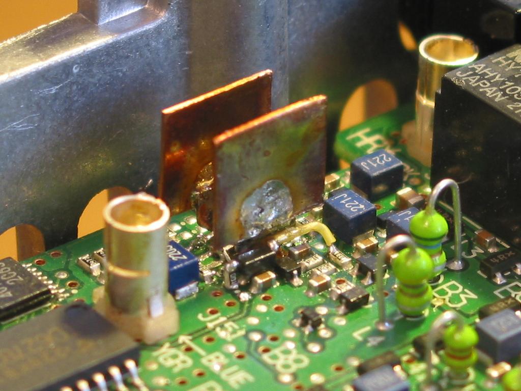
This is a view of the competed mods done to my own
746Pro..
|
Smoke Test
That completes all the mods that are known to date. Button
it
back up, put the fire to it, and if everything went right your
746Pro
is once again a happy camper. It shouldn't require any
alignment
or other adjustments. Any slight differences between the
old and
new amplifier IC is automatically compensated for since this
stage is
within the ALC loop. A while back, Allen AE0Z posted a
question
on the 746Pro Yahoo Group page
wondering if the switched TX VCC modification contributed to any
QSK CW
bit
truncation.
To verify this I "unmodified" mine, tested the CW keyup delay,
then
tested it again with
the switched TX voltage in place. No measureable difference was
noted
between
the two (about 12mS). Now, rather than push your luck
again, this
would
be a good time to install some quality DC shunt type arrestors
on the
feedlines coming into the shack, such as the ones available from
Array
Solutions.
Conclusion
It mystifies me why Icom won't
issue a
service bulletin regarding this defect. The
official company position is that it's not a common problem, but
if you
have a problem with your rig under warranty it will be repaired at
no
charge.
While this is a safe position for the company to take, it is
little
consolation
for
someone who just dropped in the neighborhood of 1.5 kilobucks on a
new
rig, and now has to pay UPS $30 in shipping and insurance to ship
the
rig
to Bellevue, WA. Plus be without it for a number of weeks
until
they
get
it repaired and returned. There
is a page at Icom's website detailing the ESD
diode
fix but they don't explain
why units with the ESD diodes
installed
are still failing. Interestingly, they state, "ICOM America
service
records show that the failure rate of this part has been reduced
to
1/10th of the previous value." Gee, they almost fixed
it.
What I found especially amusing is their mention
about
the heat issue- "Our service technicians do not see any
discoloration
of
the circuit board or the deformation of parts that are the
symptoms of
overheating." It's pretty ignorant of them to associate
melted
components
and discolored copper before suspecting an overheated component.
Why
they are so afraid of admitting any
problem
with the rig is a mystery. With such a complex piece of equipment
and
limited
development and testing budget (and likely limited profit margin
to
boot),
it's no surprise something like this could sneak past the
development
engineers.
I can accept that but repeated denying there is any fault is
insulting
the intelligence of myself and other hams out here that do design
work
and have reasonable evidence that there is a design
deficiency.
It says on the back of my Icom manuals, "Count on us!". I
wonder
what for, certainly not for customer satisfaction. Makes you
want
to buy a different brand. Problem is, it's no greener on the
other side of that fence either.
�


