 |
|
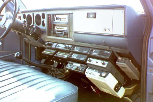
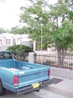
Here is my truck not long after the last radio was installed. 4 years later it is still humming along, now as an electric vehicle. |
|
|
|
Here is my truck not long after the last radio was installed. 4 years later it is still humming along, now as an electric vehicle. |
Humble Beginnings
When I got my '85 S-10 back in '86, I installed a single Larsen 5/8 wave 2M whip and my trusty Icom IC-22A crystal rig. That's pretty much the way it stayed, as I was poor and a crystal rig took care of my modest mobiling needs.
The Incremental Feature Creep Begins
Later, once out of the US Air Force and having worked for a Motorola 2-way shop for a few years, I started to acquire a few Moto radios. I added a UHF MaxTrac to the dash and drilled another hole in the roof. Having two radios is nicer than one dual-bander, I liked that flexibility.
Fast Forward to 1995.
As time went on, I continued to barter and buy more Moto mobiles. Soon I had a shop full of used, abused and bits of radios. I thought about adding more bands like 10 and 6M FM to the truck, but how would I manage all the speakers and microphones? Two is easy, three or more is not.
So after a bit of pondering and reviewing my equipment inventory, the plan began to unfold. I'd use Motorola's concept of "select" and "unselect" audio control, just like thier remote consoles did. This way I'd only need one mic, and two speakers. I'd also need a control head to select each radio so I started on that first.
 |
|
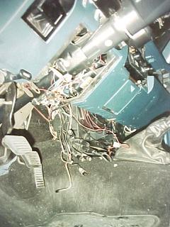
Here is the old 2M/440 control cabling. If you think this is a mess, you should see what it looks like for 8 radios! |
The Control System
I used an old Syntor Systems 90 head for hardware, since they are the same size (width and height) as the radios I'd be using. Using an old scan or channel board (I don't remember which now) as a platform, I cut islands around all the switch traces. This gave me a proper size PCB with multi-pole switches. I decided I'd need op-amps to buffer the TX audio, and a comparator to turn on an RX LED for each channel, and provide COR logic for the 440 MHz vehicular repeater. Since each radio position is exactly like each other, I just duplicated the same circuit for each one. There are only six switch positions which initially could only control six radios, but later I muxed two of the channels as "spares". These I now use for 10M SSB, my IC-735 HF rig, or just about any transceiver, giving me an 8-radio capability.
 |
 |
|
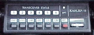
Custom Systems 90 Control Head. Escutcheon made with Corel Draw for OS/2 and a laser printer. |
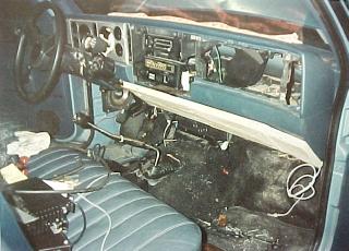
The plywood mounting surface is test fitted before painting. |
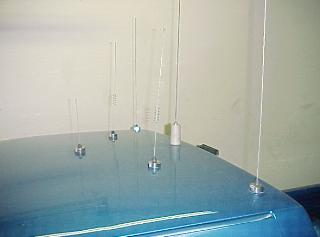
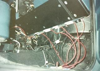
Seeding the Antenna Farm
The antennas were easy, I just decided on a triangular pattern for the 6 antenna mounts that utilized the two existing holes that were there. If there's one thing I learned working for Moto, it was how to drill a 3/4" hole. Heaven knows I've drilled hundreds. The coax was a little harder. I couldn't fit all the coax cables down one pillar, so I split them and ran them down both sides. In addition to 6 coax cables, there's 12V power for the dome light, a bed light, and a multi-conductor cable for the overhead speaker (select audio).
 |
 |
|
6M, 2M, 220 and 440. |
Bumper mounted HF Mast for 80-10M mobile. |
 |
|
Stereo amps and cabling, antenna cables coiled on right. |
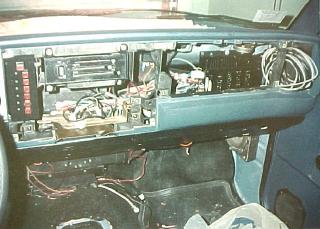
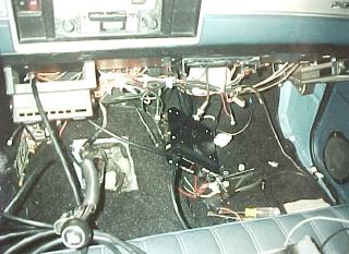
Installing the Radios
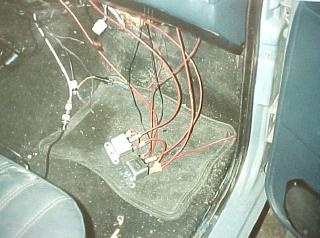
Once the control head was built and tested, the real work began. To give myself a solid platform to work from, a 3/4" plywood base was cut to fit the exact contour of the dash. Two runs of 6ga were routed from the battery through the firewall to outlet strips and fuse blocks mounted along the bottom of the dash. Here's where it started getting complicated. It would seem simple enough to just connect 12V, antenna, ground and control to a radio and do it eight times, but after about the 4th one it really got hairy. In order to save room, brackets were omitted. The radios (except #7 and #8) are mounted by disassembling the radio, screwing the chassis to the dash or the radio above it, then reassembling the radio in position. Very time consuming. Some radios needed separate switched ignition and battery hot connections, which complicated things. Seems every radio needed a different fuse, and of course each had a set of unique connectors. Two of the radios have remote heads, so I had to mount the main chassis to the floor under the seat. Plus make room for the Systems 90 siren/PA module. With power, control, and coax for two radios, plus 4 pairs of speaker wires, there's LOTS of wires under the carpet.
 |
 |
|
The two 40A A+ relays used for DC control. |
The finished plywood support, 12V fuses and terminal strips. |
 |
 |
|
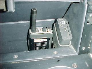
Radio fitting and cable routing. HT90 on the right is the UHF Link radio. Hands free PTT/cruise control mounted on stick shift. |
Expo portable always on charge in the glove box crystaled up for the 440 cross-band radio. |
Bringing it All Together
With all the radios mounted and antennas connected, system shakeout began. It seemed there were a zillion levels to set, and problems with cross-coupling to work out. But eventually I got it where each radio would have the same modulation as the other with the single mic, and cross-coupling was minimized in the low-level AF mixer and amplified speakers. As a bonus, my stereo had a CD player input and my control head head had line-level signals. With a push of a button my select audio comes out the left channels, and unselect on the right. Still can't think of a practical use for this, but it's neat to show it off :-).
Hey buddy, got enough antennas?
As mentioned in the QST article, the most often asked question is, "Gee, what are all the antennas for?", to which I reply, "For all the radios!" While certainly there is no legitimate *need* for 8 mobile radios and the capability to use them all at once, it sure is fun. I can be flapping on my 2M repeater and hear a call come in on 6 or 10FM, or hear a buddy call on 440. I can set one 2M rig to scan SAR or commercial channels while still monitoring 2M ham traffic on the other one. All of that, plus the nighttime illumination is *really cool*. Looks like an aircraft cockpit with all the knobs, dials and blinkenlights. I'm not sure I'd go through all this trouble to do it again but I'm glad I did it this time, it sure has gotten a lot of attention. All the way into the pages of QST !
Thanks to the Radios To Go editor Roger Burch, WF4N, for bringing my truck into the spotlight.
Read more about my truck's conversion to electric power in the EV Page of my website.
 Back to the Main Mobile Page |
 Back to the K5LXP Home Page |
 � 2026 Pane Relief Computer Services |
|