


![]()
![]()
![]()
![]()
![]()


K5JMP: News
So, you want to put in a "crank-up" tower that can be laid down to avoid climbing...
Learn from my trials as I attempt to accomplish this mission on a shoe
string budget.
First thing is to locate the manufacturers foundation drawings for the tower of
interest. My tower just happens to be a Tri-Ex W-51.
I had a very hard time finding these two drawings... seems that Tri-Ex was sold a few years back. But with a little effort and assistance from the Google search engine I found the following web site www.karltashjian.com
On that site I located the following drawing.....
I was not able to find any specific requirements for "soil stability analysis" or even what kind of soil this drawing related to. It did note "pour against undisturbed soil." With this in mind, and the number of frivolous lawsuits these days, I decided overkill was the best solution. It is also damned difficult to "hand dig" a hole 26" square X 6' deep. All things considered, and the possibility of hitting rock before the desired depth was reached, I decided to make the hole 4' square X 6' in depth. I also seriously doubt the manufacturer considered a "motorized screw-jack" assembly to lay the tower down... this drastically affects the load on the base fixture and foundation.
The next step is to get a certified copy of the "platt" for your property, and all local codes that may affect your project. Call "Miss Utility" or the equivalent in your area... they will mark all underground utility problems before you spend a lot of time digging up your yard only to say "Oh Shit!!! Where did that come from?".
This is one hell of a lot of concrete to have to take back out should someone find a flaw in your installation, get it right the first time!! Almost 4 cubic yards of concrete in my case.
Once you have decided on a location that meets or satisfies all requirements, ask one of the county building inspectors to check out your site and paperwork. You won't get a second chance, and they are not "glad" regarding code violations. Hopefully any required permits can be granted at this time. I was lucky, in my county all permanent "antenna support" structures under 30' ground to tip are exempt from this time consuming permit mess.
Next, get out some pavement marking paint.. and lay out the dimensions of your excavation area. Then grab a good shovel, and a pick axe in my case, and go to work. I found it helpful to work very early in the morning, July heat is very unforgiving. You will also notice, that no air is moving in the hole as you get deeper down... a fan is a very good idea.
In the picture below, you will notice the walls of the hole are no too straight. I waited until after the concrete form was in place to "square-up" the hole.

I hit many impediments along the way... granite was the worst. One other note: WEAR YOUR SAFETY GLASSES WHEN YOU ARE ATTEMPTING TO BREAK THE ROCKS INTO SMALLER PIECES. As you can see there is a large rock in the bottom of the hole. I made the mistake of flipping my safety glasses up for a minute while I shoveled out the loose stuff in the bottom, just couldn't see because of profuse sweating! Bad mistake, without thinking, I picked up a drillers hammer and took one more swing to loosen a rock. Needless to say, I reported for eye surgery the following Monday. A painful, and expensive lesson learned again!
As is usually the case, no one showed up to help dig... even after a week of
"mentioning" the project on several of our local repeaters....
I did, however get help from my constant companion... Casper.

Casper loves to play fetch... and was constantly dropping his "toy" into the hole to get my attention. Casper spent a lot of time looking down into the hole. Providing his own brand of "morale" support!!!
When you get a ways down, you may need to "shore-up" the hole to avoid a cave-in. I can't stress enough how important this is...Due to the soil conditions I had to work with, no reinforcement was required. I could have actually made good use of dynamite, had I been out in the country. Amazing just how difficult red clay can be in a hand digging scenario!
Once the hole is completed, you must again refer to the drawings to design a base "fixture" to set into the form. This fixture is the link between your tower and all that concrete in your very near future. I decided to "over-build" my fixture, should I decide to replace the tower later with a more robust model. The following picture is what I constructed.

Be sure to use plenty of rebar welded into place. This is a requirement to get a good "grip" on the concrete. The following picture also shows the "leveling screws" on top of the fixture. I strongly urge all fixtures incorporate this feature. No matter how much you try to hold the fixture in a static position, it will shift slightly when you make the pour. The screws allow for "plumbing" the tower once it is in place.
Once the fixture is constructed, you need to devise a way to suspend it in the hole. I would also suggest that you allow some room beneath the fixture to fill with concrete (fixture not sitting on the dirt in the bottom of the hole). This approach will keep ground water from corroding the fixture from the bottom up... which could lead to a very rude surprise in the future. Some folks suggest using hadite bricks for this purpose. I submit that this "hadite" material is porous, and defeats the entire purpose of elevating the fixture. The following picture shows how this phase of the project was accomplished.

It also shows a good look at the leveling screws I mentioned earlier. As well as Casper staring forlornly at his toy. I had approximately 6 inches from the bottom of the fixture to the floor of the hole. It also shows a trick I have used in the past.... notice in the inside corner of the form, a 2" X 2" block. I put these in here so that in the "worst-case" scenario the foundation has to be removed you can loop a cable around the foundation and pull it out with a large crane. It only took a few seconds... and you never know when Old Man Murphy is going to grace you with a visit.
I have no pictures of the cement truck, as I was quite busy at the time he arrived. I would also suggest using a piece of rebar, or pipe to "work" the concrete as it is poured into the form. It helps to get all the bubbles out of the mix. I used a 5000psi mix, and paid around 90 dollars a cubic yard. Your supplier can provide you with information regarding the best mix for your project. Don't be a hardhead... ask questions, it could save a ton of grief in the future!
I had the driver "over-fill" the form on purpose. That way I could float the surface with a little rise to the center. It will insure the top of the foundation doesn't hold water. I certainly would not want the fixture to rust away from standing water on top of the foundation!!!

As mentioned earlier, the fixture did try to shift slightly during the pour. I used a 12' piece of 1.5" X 2" square tube to add support to the fixture. Once the mix begins to set up, you can remove the additional supports. I, however had a thunderstorm move in just as I began to float the surface. Never fear! Plastic sheeting was only a few steps away...

The following evening, after returning home from work, I removed the supports and form....
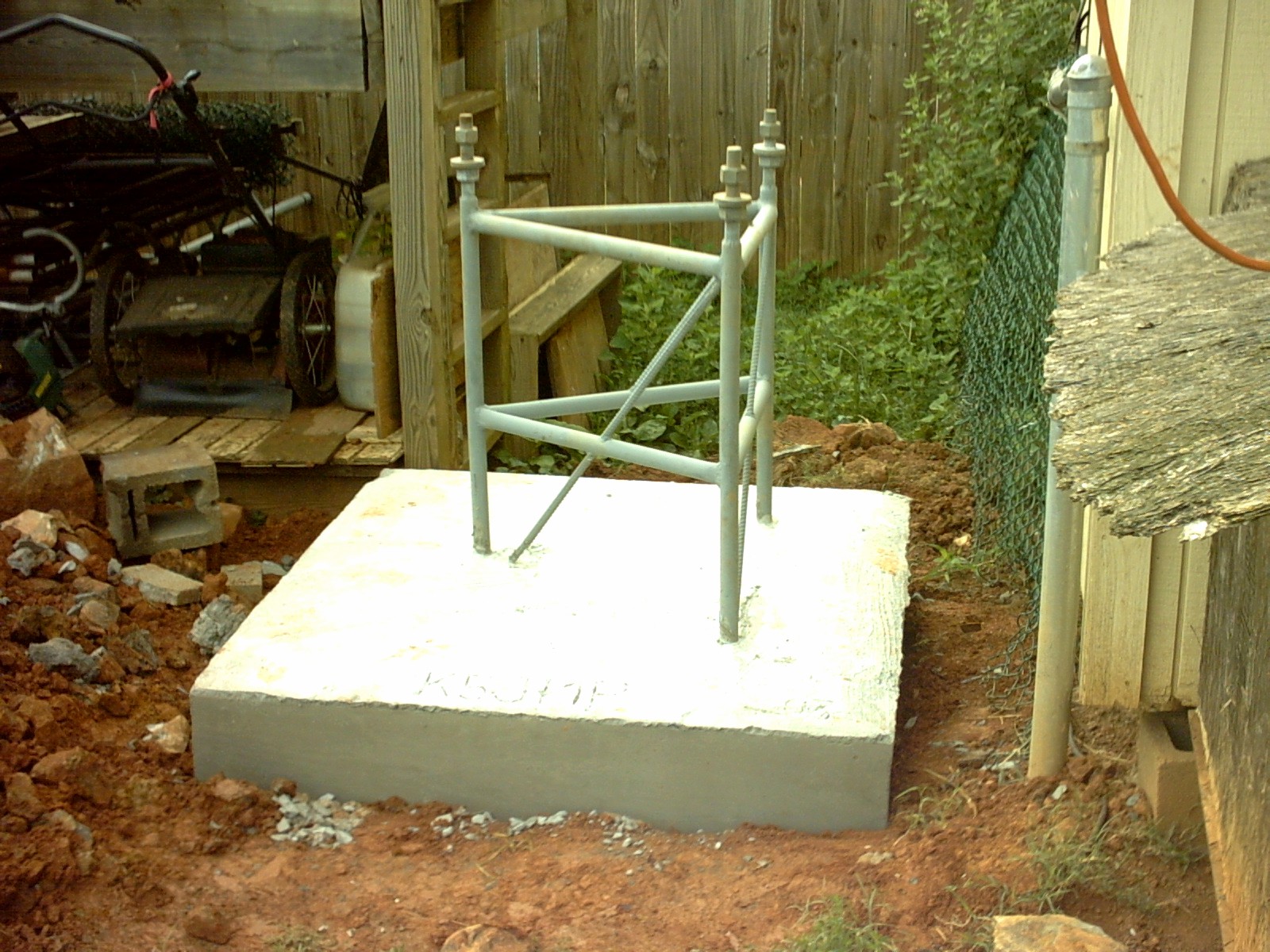
A tower footer like this should "cure" for at least a week before you try to put a load on the fixture. I would suggest checking with the concrete supplier for specifics on curing time.
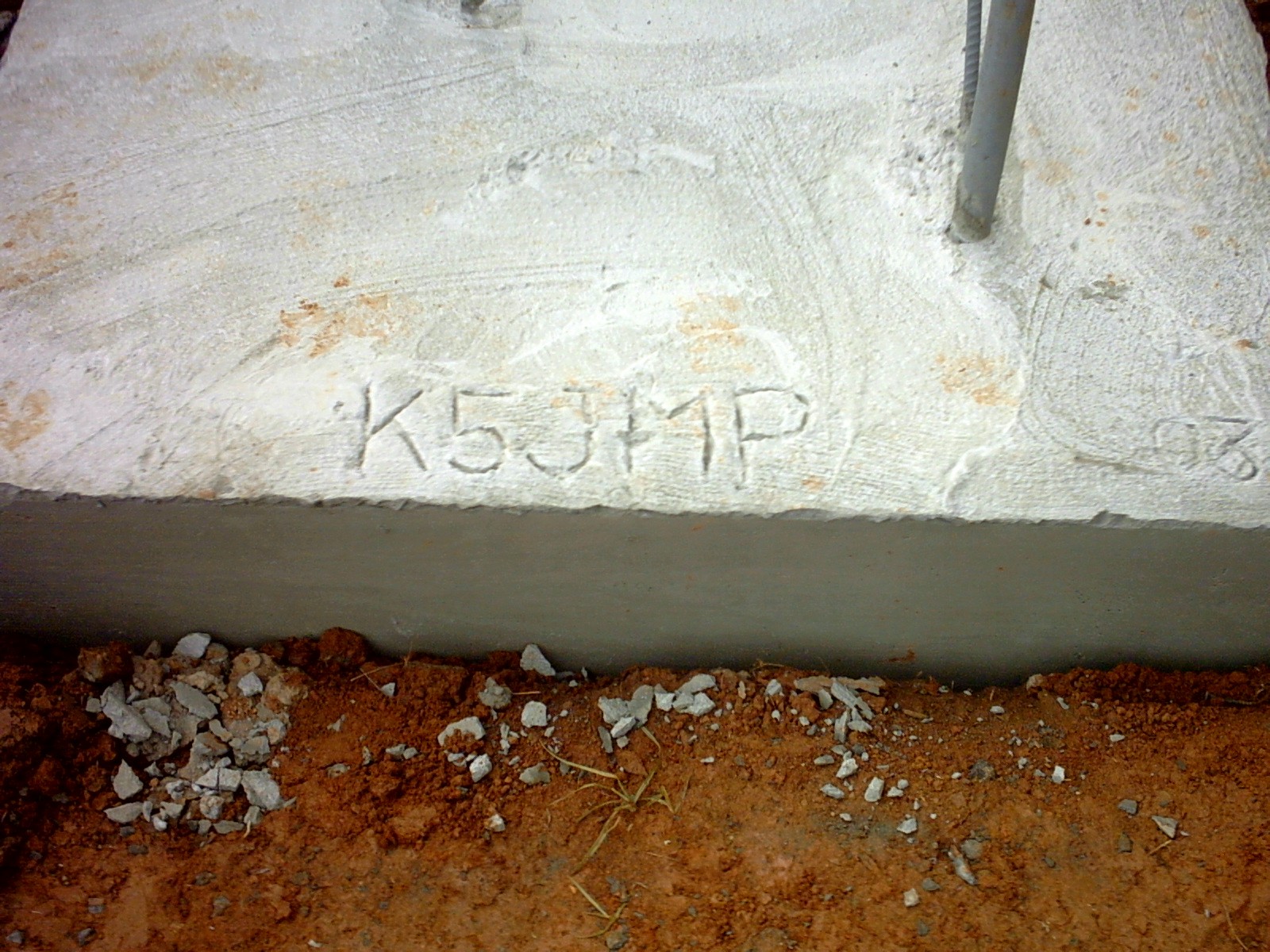
I couldn't resist the temptation to leave my call in the foundation...
I will publish more info as I develop the "motorized hinge
assembly"...
8/3/03
I was able to locate a picture of the "screw drive" and hinge plate
under development.

In the picture you will notice the six foot long screw leaning against the
Diamond Antenna box. I had to cut approx 20 inches off the top. Then weld a
grade 8 hardened bolt to the end of the screw, using a 12 foot long
"cheater bar" I managed to break the top nut loose. Then using the
torch to heat the nut, and an impact wrench on the grade 8 bolt... I managed to
separate the two pieces. Unfortunately I believe the nut to be un-usable. This
screw assembly was donated by AK1E (Tom Harmon), he said that he had
"boiled the bolt" when it was in use on his tower (over 100'
freestanding tower, that served as the inspiration for my project). Now I
understand what he was talking about. Maybe I can have another fabricated at a
local machine shop...
The piece of steel leaning against the brown shelves is a discarded hinge
design I was working on. The large black motor is a 96:1 reduction motor... it
should be plenty to accomplish the mission.
73's for now...
K5JMP
Personal Home page | News Archive | Current News | Feature Story
This document maintained by [email protected].
Material Copyright © 2004 K5JMP