Maker World - Original 3D print files for the fused box
This is a Fused Power Distribution box featuring Anderson PowerPole connectors. These connectors have been adopted
by the Ham Radio community to enable Hams to easily connect to the power sources of other Hams. Use 14 or 16 Gauge
stranded wire. 12 gauge wire will fit (barely) in the connectors but is quite difficult to work with, and is frankly �overkill�.
3D Printed Fused Anderson Powerpole Distribution Box
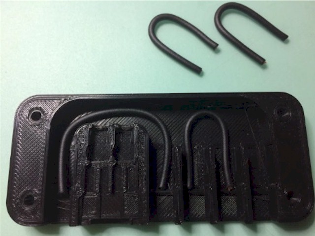
Cut the black wires to length by placing them in the shell as shown above.
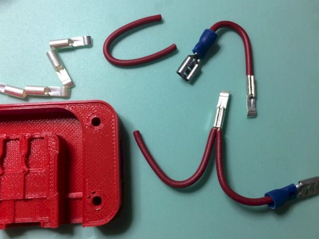
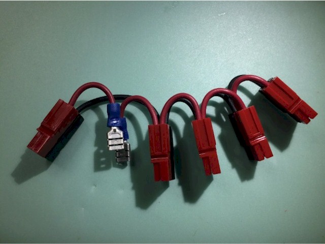
As shown above, do the same with the Red wire. NOTE: The two red wires that go to the fuse spade connectors will
be slightly shorter than the rest. Keep them separate as those are the ones that shall be crimped to the spade connectors.
On the first SHORT red wire, strip the end and crimp a spade connector onto it. Then strip the other end
and crimp a powerpole connector onto that end. NOTE: many people have made the mistake of chaining
all the red wires, then putting the other spade connector on the end, only to be confused about why it won't
all fit in the shell. The first red wire has a powerpole on one end, and one powerpole on the other.
On the 2nd short wire, Strip the end and crimp a spade connector onto it. Then strip the other end, and
strip the end of the next red wire, and put both ends into the Anderson Connector and crimp them together.
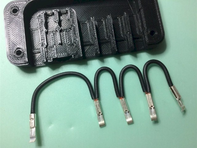
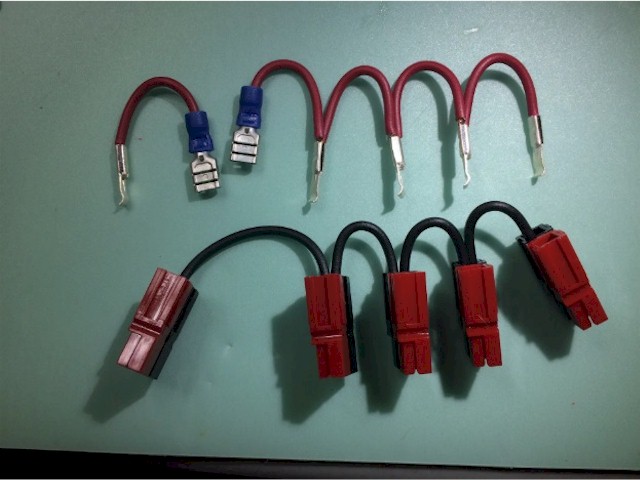
When you're done crimping the Red wires, you should have what appears in the above photo.
Do the same with the black wires, you should have what is shown above.
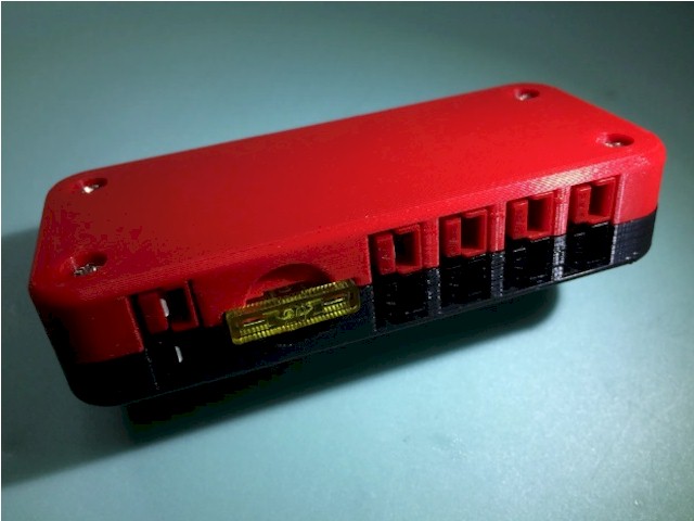
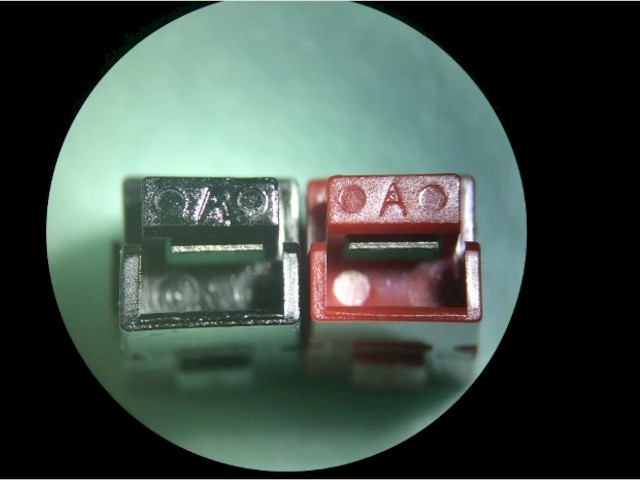
Assemble the shells together as shown above. Looking at the front, when the �A� is upright, the red shell should
be on the right side.You should have 5 pairs of shells.
Insert the Black wires into the black shells. Make sure there is a positive click and that you cannot easily tug it out.
(if the wire pulls out of the crimp, you'll need to do a better job of crimping. Using the correct crimping tool is highly advised.)
Then insert the Red wires into the red shells, giving a tug to ensure they're clicked into the shell properly and that the wire doesn't pull out of the crimp
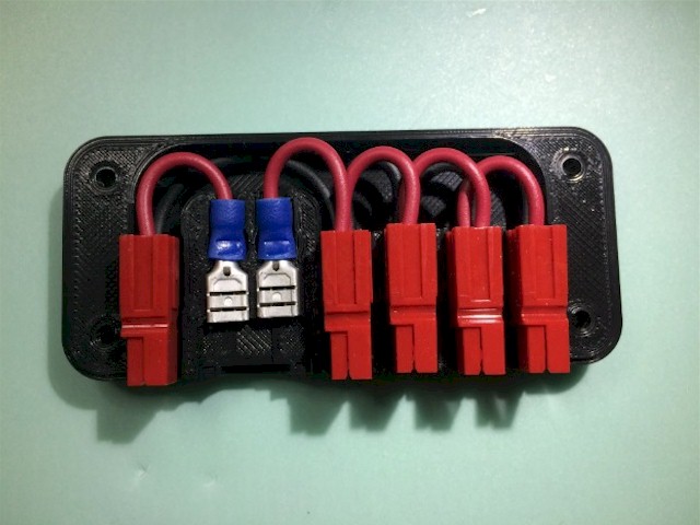
Lay the assembly into the black shell. Twist the spade connectors so that they are oriented as shown in the above photo.
Put the red shell on top, and bolt together with four M3x16 phillips head screws and nuts. Insert a 15A or 20A automobile fuse to complete the build.