I've built many transmitters over the years, but this one was definitely the most fun! It uses a 6AG7 crystal oscillator to drive an 807 final. The oscillator design is directly out of any 1960s ARRL Handbook, and the basic design for the final came from one of my favorite project books, "104 Ham Radio Projects for Novice and Technician" (TAB Books, 1968). The note and keying are about as clean as you're likely to hear from a homebrew rig.
I originally built this rig in 1998. It started out with a 6V6 in the oscillator, but I rebuilt the oscillator section in the autumn of 2003 and changed the tube to a 6AG7. In early 2004, I modified the circuit so as to allow VFO operation.
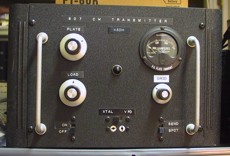
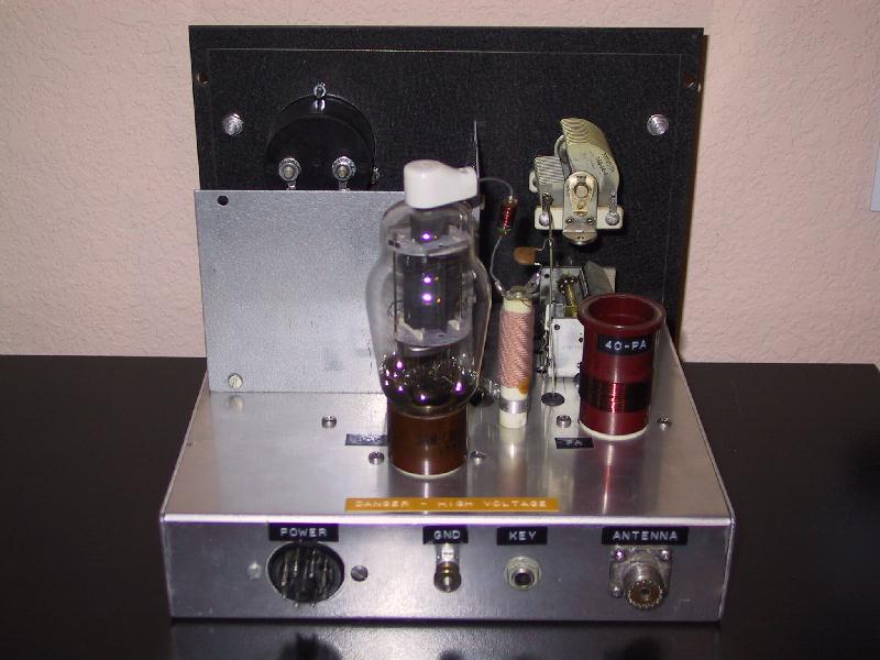
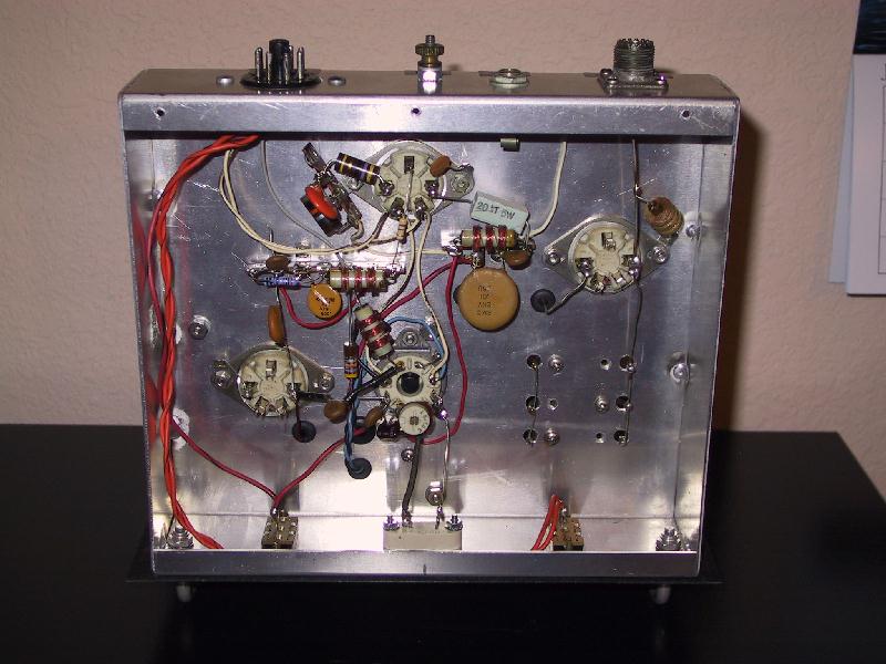
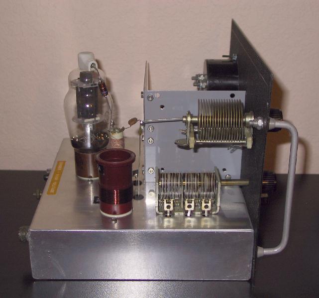
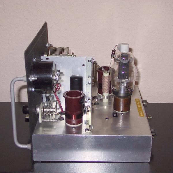
I used as many vintage parts as possible during construction to ensure that the finished product would have a 1950s look. The oscillator and PA tank coils are wound on 1-1/4" diameter red bakelite 5-prong coil forms from an unknown manufacturer. The tube sockets and coil sockets are steatite with silver-plated contacts, probably made by E.F. Johnson. The steatite crystal socket and 807 plate cap are James Millen parts. The plate current meter is war-surplus item made for the U.S. Navy by Westinghouse. The PA grid tuning capacitor is a vintage Hammarlund. The PA plate and loading capacitors were made by E.F. Johnson. The plate choke is an old Heathkit part. The handles on the front are WW2 U.S. military surplus. The enclosure is a 1950s Bud hinged-top steel cabinet with black wrinkle finish.
The aluminum chassis was made for me by Walt Martin, KB5HOV, out of 1/16" aluminum. I made the shield around the oscillator out of two aluminum Bud box lids, held together at the corner by some scrap angle brackets. Other than fabricating the chassis, I did all of the metal work and painting myself. I guess the only thing keeping the rig from looking totally 1950s authentic is my use of Dymo labels instead of vintage water-slide decals (and that's only because I haven't found any yet!).
I power this transmitter with a Heathkit HP-23A power supply. With +750 VDC on the PA plate and +260 VDC on the oscillator plate, output power is about 65 Watts.
Below are several photographs of the finished transmitter:
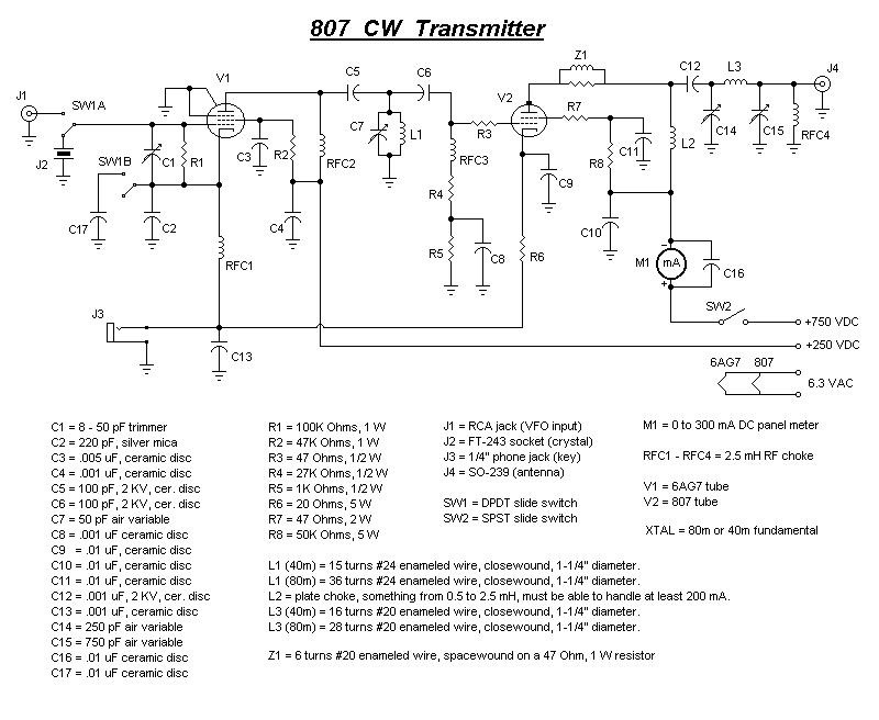
At the very bottom of the page, you will find the schematic and parts list for the 807 CW transmitter. I suggest you read the following text carefully first, before you spend any time with the schematic. There's some good information here, and some important safety information that you must not skip.
Notes:
- Plate current at maximum output power should be in the vicinity of 110 to 120 mA with a high B+ supply of about +750 VDC.
- You can use anything from +500 VDC to +800 VDC for the high B+ supply. Power output, of course, will be a function of plate voltage.
- You can use anything from +200 VDC to +300 VDC for the low B+ supply, but don't exceed +300 VDC because the maximum rating of the 6AG7 is +300 VDC.
- You can either build your own power supply or buy a commercially-made supply.
- If you want to buy a power supply, two great candidates are the Heathkit HP-23 and HP-23A. Use the 6.3 VAC output for the tube filaments, not the 12.6 VAC output! I recommend that you set the Low B+ selector to the 250 VDC position because the +300 VDC setting will probably run higher than +300 VDC at today's higher AC line voltages. You can also use the HP-23B, HP-23C, or PS-23, but you'll have to wire the tube filaments in series and use a 12 Volt pilot lamp bulb because those later models don't have 6.3 VAC filament outputs. The older Heathkit HP-20 will also work, as long as you wire it to put out 6.3 VAC for the filament voltage. The much older Heathkit UT-1 will work, although the High B+ is only +600 VDC, so your transmitter output power will be substantially reduced. As with the PS-20, be sure to wire the filament output for 6.3 VAC. The Heathkit HP-23 and HP-23A supplies are quite common, easy to repair, and don't cost an arm and a leg, so they're really a good choice. Other vintage power supplies should work fine, too, as long as they meet the voltage and current requirements for this project.
- If you want to build a power supply, refer to older editions of the ARRL Handbook from back in the "vacuum tube days". Make sure that your chosen power transformer can supply enough current to power the oscillator and power amp. Look for one that can put out at least 150 mA. If you have a large enough chassis and cabinet, don't be afraid to build the power supply into the transmitter.
- You will find the tube pinout information in any older edition of the ARRL Handbook, GE or RCA Vacuum Tube Manual, etc. If you don't have an old Handbook, GET ONE. They're readily available on eBay and at hamfests. Until yours arrives, you can pay a visit to your public library. They should have one.
- Trimmer capacitor C1 should be adjusted for the least amount of crystal "chirp". Although a value of 8 - 50 pF is shown in the parts list, anything in that general range will work fine.
- Feel free to install several different types of crystal sockets, wired in parallel, so that you can use different holder types. The most common ones will be the ol' faithful FT-243 and the more modern HC-33/U, and you might want to include one of those big ol' sockets for BC-610 crystals. Alternatively, you can make up some adapters, which is what I did. Having more than one socket type means that you'll have more chances of finding crystals that you can use. Don't bother with those tiny little HC-18/U and HC-25/U crystals (the kind used in CB radios, scanners, and so on). They aren't designed for the kinds of voltages that this transmitter will present to them.
- SW1 is the "XTAL / VFO" switch. Setting the switch to the "VFO" position converts the 6AG7 oscillator into a buffer stage. The 0.01 uF capacitor that is switched into the circuit kills the tendency for the 6AG7 to oscillate.
- SW2 is the "Spot / Send" switch. In the "Spot" position, it allows you to key just the oscillator so that you can find your signal with your station receiver. In the "Send" position, the PA becomes active as well.
- The oscillator stage is the classic "Grid-Plate" oscillator from the ARRL Handbook. For best performance, the ARRL recommends that you stick close to the component values shown in the parts list for the oscillator stage. I've found their recommendations to be correct.
- When you choose your fixed-value capacitors, be mindful of the DC and RF voltages which could be present in the circuit! I suggest you use caps with at least a 1 KV rating for those parts whose ratings aren't otherwise specified.
- I recommend that you make the 80m and 40m coils interchangeable so that the rig will work on both bands. There are several ways you can go with this. You can use vintage plug-in coil forms, which require a matching socket (you'll find 4-, 5-, and 6-pin styles out there). You can use octal tube sockets and tube bases (salvaged from some old "dud" tubes). You might get lucky and find some vintage ceramic James Millen jack-bars which will allow you to use B&W or Air-Dux coil stock. Just use whatever you can find, but be sure you can find enough to handle the number of coils you intend to use (two per band!).
- If you find coil forms that are some diameter other than 1-1/4", that's no problem. You'll just have to re-calculate the coil parameters. You'll find the formulas for calculating coil parameters in any ARRL Handbook (how's your high school algebra these days?). No, I will NOT help you do this. If you don't already know how, then you need to learn how. I'm not trying to be a "meanie". If you plan to build equipment like this, you'll have to know this stuff anyway.
- If plug-in coils aren't your thing, you can always come up with some kind of band switch arrangement. You'll need to be able to switch both the oscillator and PA tank coils. You could use separate switches or a multi-deck switch for this.
- No, I don't know where you can buy these parts, so please don't ask. You'll have to scrounge for them, just like I did. Where should you look? Hamfests, surplus stores, electronic parts catalogs, other hams' junkboxes, eBay auctions, For Sale listings on QRZ.com, QTH.net, and the Usenet newsgroups, and so on. I often buy other hams' old homebrew projects and old military surplus equipment and strip them for parts. Hunting for the components for a project like this is a big part of the fun! Besides, nothing truly rewarding ever comes easily. The harder you work for something, the more it will mean to you in the long run.
- You'll need some means of switching your antenna between your receiver and the transmitter. Go figure it out.
- Don't try to use your typical electronic keyer with this cathode-keyed circuit unless your keyer has a keying relay or a really stout keying transistor that's rated for high voltages and high currents.
- Tuneup is simple. Set C7, C14, and C15 to mid-range. Connect the transmitter to a suitable antenna or 50 Ohm dummy load. Plug your Morse key into J3. Apply power to the transmitter and let the tube filaments warm up for a minute or two. Set SW2 to "Spot" and hit the key. Tune in your oscillator signal on your station receiver. While listening to the receiver, adjust C7 for the loudest signal. Let off the key. Set SW2 to "Send" and hit the key. Watch the plate current meter and adjust C14 for the LOWEST plate current (known as the "dip"). Adjust C15 to bring up the plate current by 10 to 20 mA, then dip again using C14. Repeat this alternating process until you're loaded to 110 to 120 mA output. You can watch your Wattmeter also. When bringing up C15 no longer increases your power output, you're fully loaded and there ain't no more power gonna come. In any case, C14 will always be your last adjustment of the PA stage. If your keying sounds chirpy, you may need to touch up a bith with C7.
This project involves LETHAL power supply voltages. You must use great care when working with this circuit. Never forget that death is a permanent condition! Any homebrew project like this might involve troubleshooting a live circuit. If you don't feel comfortable working with high voltages, then you should either forget about messing with tube-type equipment, or get friendly with a local ham who is experienced with this stuff and ask them to assist you and teach you what you need to know (this person is known as an "Elmer", and every ham, new and old, should have at least one!). I recommend the latter. Never be afraid to ask for help! It's much better to feel stupid for asking than to BE stupid and get yourself killed because you didn't ask!
If you use plug-in coils, you MUST turn off the power to the transmitter and allow the power supply filter caps to discharge completely before you change coils! A good way to quickly discharge the filter caps is to switch off the power supply, switch the transmitter to the "Send" mode, lock your key in the "down" position until your signal has disappeared completely from your station receiver, then wait another 30 seconds.
It seems really silly to me to even have to mention any of this, but I just know that some knothead would kill himself changing coils if I didn't!