Low Voltage (12VDC) Two Tube Regen Receiver Using "Space Charge"
Technology
Before I go into the details, let me say that I've built about 1/2 dozen one and two
tube Regens over the years (and several superhets) and this one is by far the most
selective, most stable, and easiest to use Regen. The 12AL8 and 5687WB
or 7044 tube combinations work well, as does the 12AL8 and 5814WA (12AU7)
combination with the plate voltage reduced to around 8V. Copying CW and SSB, as
well as AM SW stations is easy. I have not had a chance to try more of the MANY
other dual triodes like the 12AT7, 12BH7A and they may all work as well. I'll expand
this write-up as other items come to mind.
There will be a low voltage (24V ? 48V ?) CW transmitter to follow.
This was a fun project and all started when I was looking for low voltage designs
for a Regen Receiver and matching Transmitter. Several of the guys on the Glowbugs
(GB) Reflector reminded me of "Space Charge" tubes developed in the 60s to make
car radios which did not require vibrators (used a power transistor for output). Their use
was short lived with the advent of fully transistorized radios. The concept was actually
invented in the 1920s but I don't know how widely it was used.
Normally, tubes operate with hundred(s) of volts of plate potential or around
a hundred volts for battery tube sets. To ask them to work at very low voltages,
something has to change because the lower cathode to plate potential is just not
enough to enable enough current flow. The other problem is that the plate curves
appear to become very non linear at low voltages. One method of improving the
electron flow is to change the spacing and physical design of elements inside the tube.
Another is to "boil" more
electrons off the cathode by increasing the wattage of the filaments through redesign.
A third is to place the 1st grid at B+ potential, thereby providing a nearby "pull" on the
electrons from the cathode. Since it is a "grid", many of the electrons reaching the 1st
grid zip right on through. The second grid (screen) is used as the "control grid" and
the B+ charged plate gathers up the electrons. There is no suppressor grid.
The disadvantage of these low voltage tubes is that they consume lots of 12V
power, which
for a car radio, does not matter. For example a "normal" dual triode, miniature tube,
may draw 150mA of filament current ......these may draw 350mA. The "space charge"
Tetrodes may draw 500mA+ filament current. In addition, the Power Tetrodes with grid 1
tied to B+, may draw 70mA on the grid (not useful power, not input controlled) and half
that on the plate (input controlled and useful). While this makes them very safe to use
from a voltage standpoint, it does generate heat and they do get HOT. The reduced
spacing between elements increases inter-electrode capacitance which reduces their
usefulness at RF frequencies but they work well at AF frequencies. While all this is
required in the "POWER" sections like the AF amplifier, it's NOT necessarily required in
the low power VOLTAGE amplifier sections like the RF/IF Amplifier and the Detector
in a car radio, or any other radio for that matter.
DESIGN CRITERIA:
- NO VOLTAGES ABOVE 14VDC .........anywhere
- Power by: 12VDC wall wart, 13.8VDC power supply, 12V gel cell, 12V car
battery
- An RF amp for isolation to prevent unnecessary radiation
- Allow for some design experimentation so it's both a useful radio and "test bed"
- Allow for both 9A and 9H based dual triodes
- Bandswitching, no plug-in coils, no extra parts to get lost
- Ham Band only focus via good bandspread tuning capability, will cover SW
- Smooth tuning, sufficient volume, and less critical Regen adjustment
- Incorporate many of the design "Do's" from the Regen experts
- Something different .....but for good reasons. Not a reproduction of someone
else's radio. "Interesting"
Basic Regen design is pretty common, so BEFORE the schematic
comes the "concept stage", the "what's available in the junkbox stage", back to the
"concept stage", followed by the "mechanical/electrical layout stage", then sketch a
rough schematic ......and do it all over again. Paper/Computer layout is cheap.
After researching the "space charge" tubes, it was decided to go with the 12AL8
triode/power tetrode combination. These tubes are readily available and I found some
NOS for $2 or $3. The Sylvania specifications for the tube (available online) also show
a handy audio circuit which I used .....after a few modifications. It uses the triode as an
AF voltage amplifier feeding the power tetrode.
For the Regen and RF amp, I looked for dual triode tubes likely to "boil" electrons
with higher filament currents. The first ones found are "computer tubes" the 5687 and
7044. These are said to also be very low noise types ? I don't know relative to what.
The 5687s are more readily available since audio guys use them, but both types are
available NOS for $2 or $4. Since there are MANY dual triode miniature tubes out
there (12AT7, 8414, 12AU7, 12BH7A, 12BY7, etc), why not make the design able to
use as many as possible ? The two basing diagrams most frequently seen are 9A/9AJ
and 9H, so why not a switch to change between the two pin configurations ?
Turns out, only the plate and cathode of one triode section require change. I used the
"stable" triode for the Regen section and the switched triode for the RF amp.
The other thing to keep in mind is that the requirement for "more power" is true in
the "power" sections like the AF amplifier, but it's not necessarily true in the voltage
amplifier sections like the RF amp and the Detector. What you are looking for there are
good low plate current/voltage characteristics (curves). Tubes like the 12AU7 and its
ruggedized 5814WA work fine ....with reduced plate voltage. The advantage of these
tubes, over a 5687WB or 7044, is that you save 300mA of filament current and reduce
the total Regen power from 1.1A to 0.8A.
The coil and tickler were wound on a ceramic ARC-5 Tx oscillator coil form.
Any circuitry associated with the Regen section should use ceramic where you can,
short leads, stiff wire, good wiring practice. If you take a look at the pictures, the
wire going to the "Frequency Set" and "Frequency Adjust" capacitors is #18 solid
wire suspended --OFF-- the chassis. This reduces the capacitive changes caused by
slight wire movement. The capacitors are VERY solidly mounted to BOTH the front
panel and the chassis.
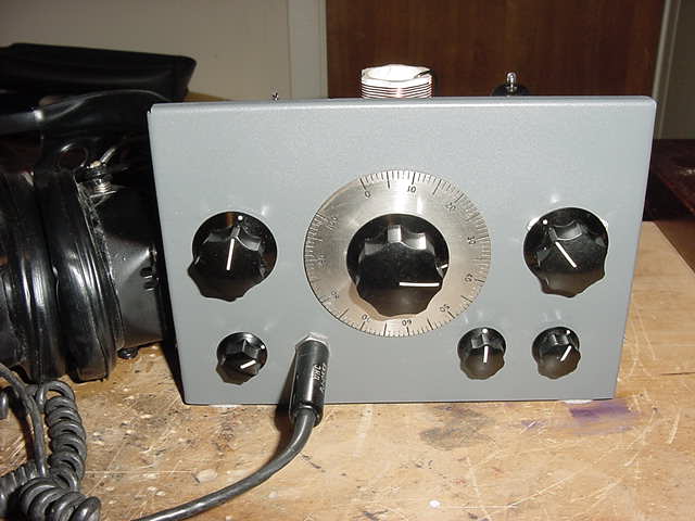
CONTROLABLES (L to R):
- Front Panel: Frequency Set (150pf), Frequency Adjust (15pf), Regen Adjust
(355pf or 110pf "Throttle" capacitor) , RF Adjust (1K), Regen Set (1K, 6-12V) , RF Set
(2K, 0-12V)
- Top Chassis: Bandswitch Select (2.5-6Mhz, 6Mhz-13Mhz, 13Mhz-22Mhz,
RF Coupling (1-7.5pf), Tube Basing Select (9A or 9H), Throttle selection (550pf or 110pf)
- Rear Chassis: 12VDC wall wart socket, 12VDC terminals, BNC antenna connector
OPERATION:
- Power should be held to 13.8VDC Max. The consumed current will go up
with increased voltage and shorten tube life. The Regen uses about 1.1A with the
highest current draw filaments. There is also a 100mfd capacitor across the power
input so there will be an initial current surge over 1.1A to the cold filaments. This will
settle down to around 1.1A (or 0.8A if using the 150mA filament dual triodes).
- Select the desired band with a jumper (see picture). If you are using the lowest
band, store the jumper wire end inside the coil form.
- Set the "Throttle" capacitor to mid position, advance the "Regen Set" until you
hear regeneration start, and use the "Throttle" to control regeneration.
- Use the "Frequency Set" to roughly tune in the signal and the main "Frequency
Adjust" as the bandspread tuning.
- Minimize the "RF Coupling" for best selectivity, adjust volume with the "RF Adjust",
and set the "RF Set" for just before cutoff (try, you won't miss it).
- If the 1K "RF Adjust" resistor provides any type of frequency "tuning", the 2K "RF
Set" resistor is not set correctly. It's easy to turn the untuned RF amp into a "diode
detector" and swamp the Detector stage with the strongest local broadcast station(s).
It's also easy to re-adjust the bias correctly to make it an RF amp only.
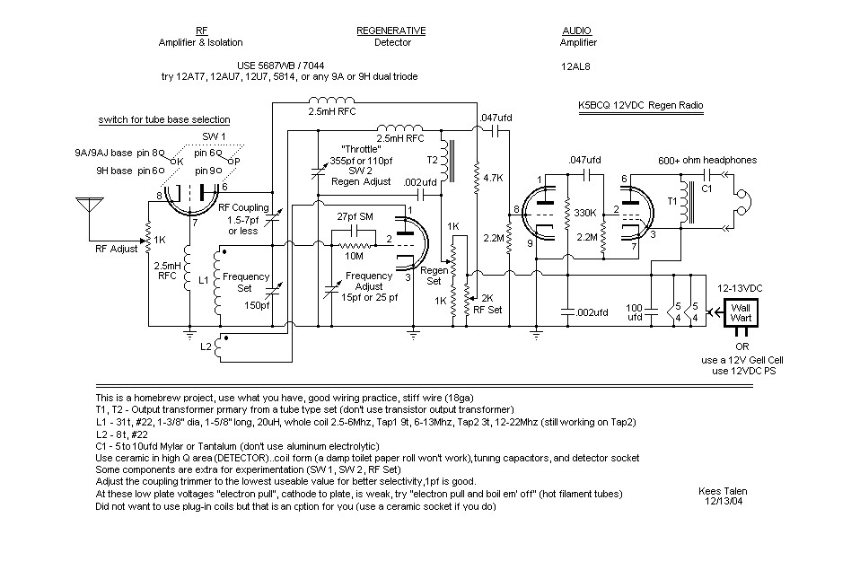
Schematic
WHAT ? & WHY'D HE DO THAT (L to R) ?
- Chassis size ...that's what I had. It's built on a used 5" x 7" aluminum chassis
picked up at a swapmeet. The 5x7
has a nice aspect ratio, so the front panel is also 5" x 7". Also found a 7" x 7" used
aluminum chassis which will be for the matching Low Voltage Tx (same type front
panel).
- I wanted the grid of the RF amp to have ONLY the bias level established by the 1K
cathode resistor on it, not any potential RF from the ground to "control" the signal, so
a RF choke was added. You can also tie it directly to ground or through a x00K
resistor but I believe the RF choke is better.
- A switch was added to allow use of both 9A base tubes and 9H base tubes. Since
only one section of the dual triode was affected, that section was used for the RF amp.
Would have preferred to use a ceramic switch but didn't have one and it's not necessary
for the RF amp. DON'T add extra wiring to the Regen section if you can avoid it.
- The RF Coupling capacitor should be as small as possible and two short parallel
wires (not twisted) works fine. You are looking for 1pf to 2pf optimum. In fact, just
bringing the antenna close works.
- A x0K RF plate resistor was originally the only component between the plate
of the RF amp and B+. Turns out, cutoff with 12V is at about 2-4K and that is not enough
RF isolation so a RF choke was added on the plate side. Since the current draw is not
that high, a resistor voltage divider was used to vary the B+ to the RF amp and to control
cutoff. Again, this is to allow more tube substitution flexibility. Power consumed by the
two voltage dividers is less than 1% of total power consumed.
- Use ceramic forms/sockets in the Regen section because of low loss (promotes
high "Q"), and rigidity (promotes stability). Low B+ helps too.
- The grid R/C is 27pf (may try less) and 10M (may try more).
- Coil data is on the schematic and is pretty straight forward. You can see most of
the detail in the pictures.
- The "Regen Adjust" Throttle capacitor has a switch to select between the 355pf
section and the 110pf section. In fact, the contacts were extended and it now has a
middle position which selects both for 465pf. This is largely for experimentation and
only using the 355pf unit or the 110pf unit is fine.
- Notice in the pictures that the wiring in the Regen section is with large solid wire
for rigidity. The Regen section wires are routed away from the chassis and other
metal as best can do, to lessen capacitive effects (IMPORTANT). A bouncing wire
1/16" from the chassis has MUCH more effect on frequency than a bouncing wire 1/2"
from the chassis.
- The "Regen Set" control was added because the feedback could not be
controlled on the higher bands with the fixed 8t tickler coil and to allow more tube
substitution flexibility. Ways of
reducing feedback are; less Throttle capacitance, fewer tickler turns, further tickler
separation ....all of which were not options. I could put a variable resistance across
the tickler, or add tickler taps, or I could vary the voltage. Turns out that a reduction
of about 1.5V to 10.5V makes it work fine. In order to allow experimentation a 1K pot
with a 1K fixed resistor were added to give 6V to 12V adjustability range. This comes
in really handy when using tubes like the 12AU7, which seems to work best with 8V
on the plate in this design (fixed 8t tickler coil). You can also use this as the
Regen control but the Throttle capacitor is "smoother".
- Didn't use tube shields because these puppies run HOT as is. The partial
"shield sockets" are sufficient because they DO provide shielding in the critical tube
radiation area ....the bottom of the tube envelope.
- T1 and T2 are both small tube type audio output transformer primaries (insulate
and fold the secondary underneath). Choke coupling is used because I had the
transformers and the plate load for the output stage is 800 ohms (didn't have a 1:1
audio transformer or a 800 to 8 ohm transformer). The military
surplus headphones I have are 600 ohm and I prefer not to pass DC through them.
Found out from the experienced guys on the Glowbugs reflector that can demagnetize
them ....didn't know that.
- Old rule of thumb ...for audio circuits the coupling capacitor and load Time
Constant (TC) should be about 0.02 to 0.1 for proper low end roll-off. In other words, a
coupling cap of .047 and a grid resistor of 1M is "0.047" ....within the range. Notice
that the values used in the resistance coupled AF section are .047ufd and 2.2M or
"0.10" ....just fine. The headphones are around 600ohms and would require a coupling
capacitor of 33ufd. Since we're not into Hi-Fi and don't need 10Hz response, 5-10ufd
is perfectly fine for CW, SSB, and good AM. But .047ufd is NOT FINE. If the
headphones are transformer coupled, there is no coupling capacitor.
- For audio signals, Mylar capacitors are excellent, poly capacitors are very good,
and for higher values the tantalum capacitors are good, aluminum capacitors are bad
due to the higher effective series resistance (ESR). I happen to find a 6ufd Mylar and
used it.
- What's that big piece of metal underneath, under the tuning capacitor ? That's to
make the mounting to the aluminum chassis more rigid. There are also mounting slots
in the chassis to allow you to move the tuning capacitor forewords and backwards for
alignment with the front panel.
- The tuning mechanism is out of my junkbox (don't know what it's out of) and uses
a 6:1 Jackson Bros ball vernier and a set of anti-backlash gears. Tuning is smooooooth.

Top view showing adjustments
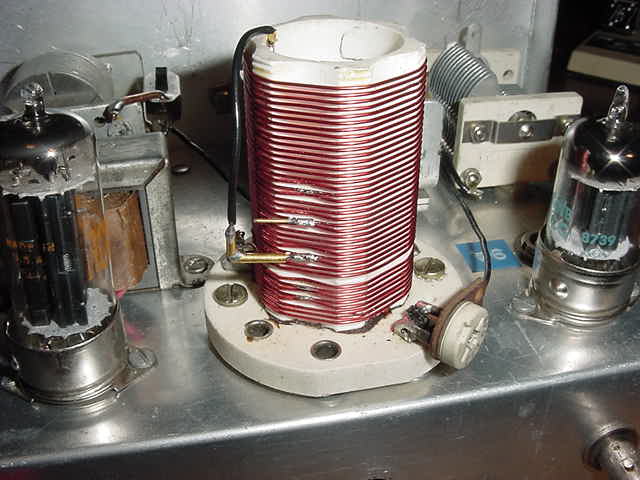
Coil bandswitch detail
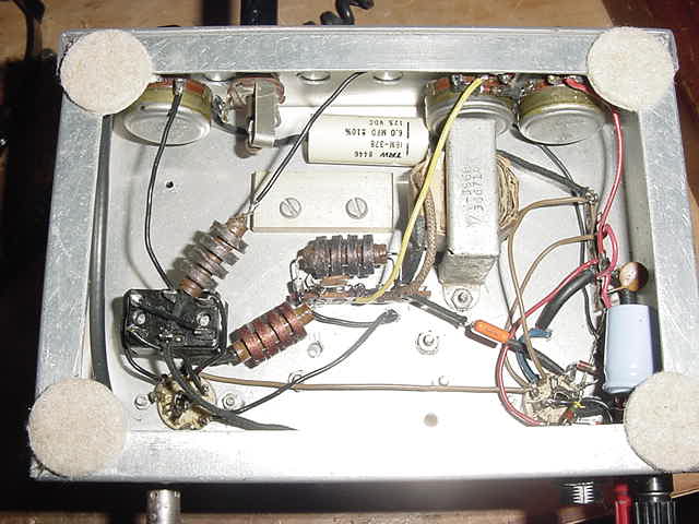
Underneath chassis detail