Safety
Go To H&K IndexAlways install a 3-wire power cord on any old receiver with a transformer in the power supply for safety and remember that several of the HBR above chassis points have up to 250V B+ on them (coils, S-meter terminals, 1st IF trimmer shaft, switches/controls mounted above the chassis).
Where to find HBRs
Go To H&K Index
The best places to locate parts for these receivers is by going to swapfests
and digging through the boxes (usually the ones under the tables) or to
locate a partially built or "needs work" HBR radio. I'm told, one
ham recently found a partially built HBR-8 for $2 at a swapfest (I think
this is somewhat unusual, but does make for a good story).
Mostly complete (but may not be working) HBR radios run around $30-150 but
prices can vary greatly and are highly dependent on "what's there" (cabinet,
workmanship, extra coils, Eddystone dial, documentation, etc). Partially
built receivers can be great sources for needed parts to build your own HBR
receiver from scratch or to debug/modify into what you want.
Circuit corrections/improvements
Go To H&K IndexBe sure to implement all circuit corrections/improvements for optimum receiver performance. It's a really fine receiver when done correctly.
The following is a compilation of required circuit changes:
- HBR-14
- Change 2nd Osc load resistor from 15pf to 5pf.
- Change Mixer screen resistor from 33K ohms to 120K ohms.
- Change Mixer cathode resistor from 75K ohms to 10K ohms.
- HBR-16
- Add a 56 ohm parasitic suppressor resistor between the grid (pin 1) of the 6BH6 BFO tube and the 250pf capacitor.
- Shield all three leads from the BFO (signal, B+, and filament)
- Make sure the BFO is actually tuned to 100Khz (see "Hints and Kinks" paragraph on JW Miller BFO coils)
- To prevent 6BE6 Product Detector overload on strong signals:
- The injection grid resistor (22K ohms) should go from the grid of the 6BE6 (pin 1) to ground, not the cathode.
- Change the 6BE6 cathode (pin 2) resistor from 220 ohms to 270 ohms.
- Change the 6BE6 input grid (pin 7) capacitor from 22pf to 10pf.
- Change the 6BE6 input grid (pin 7) resistor from 82K ohms to 22K ohms.
- Change the RF filter in the audio line from 250pf/56K ohm/250pf to a 2.5mh RF choke in series and one 250pf capacitor to ground (on the 1st audio amplifier side of the choke).
- Add fast/slow AVC by changing the 0.5mfd paper/mylar capacitor to selectable .05mfd and .25mfd values (as well as ground for AVC "off").
- HBR-11/12
- The leads between the antenna-terminal strip and the antenna-coil socket should be reversed (lead shown to pin 5 should go to pin 1, etc).
- Change the V3B Second Mixer screen resistor from 180K to 120K.
- Change the V2B First Mixer cathode resistor from 5.6K ohms to 2.2K ohms.
- Change the V7 screen resistor from 33K to 22K, 1 Watt.
- T4 should connect only to pin 5 of V6 (like on V5), not pin 6 also.
- The McCartney schematic (p42 April 1963 QST) does not show the 250pf mica bypass capacitor from the lead between S7B and R4 to ground.
- Change the 56K ohm RF filter resistor in the lead to the 1st audio amplifier to a 2.5mh RF choke (helps AM audio high frequency response).
Suggested receiver build/debug sequence
Go To H&K IndexConrad (W7WLM) suggests to wire and test/debug the receiver from its OUTPUT toward its INPUT - not the other way around. Don't just sit down and wire the whole thing up and expect it to work. If it does (which is very commendable and unusual) that's great. If, however, it doesn't work, the builder is very likely facing a big can of worms in trying to figure out why it is not working.
This technique is very valuable to employ when building "experimental" receivers.
- Build the power supply and get it working.
- Build the audio output amplifier and get it working.
- Build the next forward audio amplifier and get it working.
- Continue in this fashion, stage by stage, until the very first stage of the receiver is working.
- Hook up the antenna and you have got a functioning receiver (hopefully)
Receiver Design Additions/Improvements
Go To H&K IndexMuch work has been done to improve the HBR Product Detector. An excellent, low noise tube, which has been used by many, is the 7360, but they are expensive and difficult to find today. The 6JB8 is another low noise tube which could be substituted (circuit is the same, pinouts different). The 6BE6 in the HBR-16 is a good Product Detector but requires the circuit corrections discussed above (item #3) to prevent overloading.
A 6BY6, as used in the later HBR Receivers, may also be substituted for the 6BE6 Product Detector in earlier HBR-16 receivers. There are some component value changes required. See June 1962 QST article, p.59, for details.
Bill (W7QBR) suggests the following: "The Q-multiplier was the most useful addition. It really helped in the CW mode. The noise limiter was the least useful because it simply did not work very well. On some types of noise it was fine but on most it was just something that reduced the signal".
Bill also added a mode select switch (eliminating the need for a BFO pitch control, a BFO on/off switch, and an AM/SSB switch), eliminated the headphone/speaker switch, as well as redesigned the AGC circuit and redesigned the Product Detector circuit for a low noise 7360 tube.
Darrell (WA5VGO) implemented the "Hang AGC" circuit on his HBR-11 as described in Bill McKay's (W7QBR) article. A picture showing the AGC installation (added minibox in the center with two 9 pin tubes and transformer) is listed below (Picture/Data Links) and these are Darrell's observations/conclusions:
- As a result of the amplification, it definitely has a better handle on the receiver when dealing with strong signals.
- It works better at this time when attached to the output of the IF instead of the detector (6BY6). There is BFO leakage through the detector that finds it's was into the AGC causing some desensitizing of the receiver. This may be a result of the layout of my particular receiver and may not be typical. I may install better filtering on the detector's output or maybe even a 100 kc trap to see if that will take care of the problem. It also seemed a little slower an attack when attached to the detector. This caused the all too familiar "pop" on the first syllable. It is much less pronounced when using the IF. I guess this could somehow be caused by the BFO leakage, but I doubt it. This type of problem is typical of the audio derived AGC's I've had experience with.
- The received signal is clean, distortion free and is a clear improvement over the stock AGC. It was definitely worth the effort.
Replacing the 5V4/5Y3 with 2 diodes is a great idea - it reduces the heat immensely. If you want to retain the 5V4/5Y3 tube socket, just mount two diodes with at least a 800 PIV rating in an old octal tube base. For new builds, you should use silicon diodes. This brings up another point ...line voltage. To compensate for increased consumption and to lower current (for the power company), typical line voltage has continued to increase (mine measured 123VAC). This results in higher B+ levels, more heat, and greater chances of componernt failure. Replacing a rectifier tube with diodes also results in higher B+ voltage levels. Keep this in mind when powering older tube equipment and use a Variac or adjust power supply resistor values to compensate.
Arnie (CO2KK) suggests using a three pin regulator to provide DC filament voltage to the RF and Mixer tubes to improve signal to noise ratio. He has found 5.9VDC to work best in his homebrew receivers.
Receiver stability
Go To H&K IndexStability can be enhanced by making sure things in the front-end can't physically move. It only requires a little movement to cause a frequency shift. Bill (W7QBR) made the following comment on HBR stability: "The thing I remember most about my second receiver was that the improved mechanical stability made all the difference in the world how the receiver worked overall. The tensioning of the wire on the coil forms was another thing that I did better the second time. The coils were very stable and rugged when done correctly".
A few additional stability enhancements:
- Make sure the coil sockets are mounted solidly, the tightly wound coil wires and trimmer cap should be held in place using epoxy for the trimmer and coil dope or clear finger nail polish for the wire. Also, make any coil shield(s) sturdy so they can't move relative to the coil. Check the trimmer and coil windings periodically to see if they have come loose.
- The tuning capacitor shaft should be accurately aligned with the coupler on the dial mechanism. Any binding will cause front panel movement to be transmitted to the tuning capacitor shaft.
- Rotate the front-end tubes and coil sockets to allow the shortest wiring between them (covered in the "HBR Notes"), keep ALL wiring leads in the front-end short, and use heavier gauge wire to reduce movement.
- Install small triangular aluminum corner braces inside the bottom lip of the chassis. You will be surprised how this helps stiffen the chassis.
- Adding a bottom plate to the chassis accomplishes the same thing as the corner braces and will provide additional shielding.
- For critical tuned circuit capacitors, use only high quality micas and silver micas.
- Temperature drift can be improved by reducing the heat generated (replace the rectifier with silicon diodes, make sure the B+ isn't too high, etc) and by increasing airflow inside the cabinet (drill 1/4" holes along the chassis in hot spots).
- Use of temperature compensating capacitors is discussed, with specific examples by W6HHT, in the coil winding information in the Picture/Data Links section. Selecting the correct values for your receiver will generally require a little experimentation.
- The tubes will run cooler (and last longer) without tube shields. The tube shield sockets with the 1/2" high metal ring are generally more than adequate for most shielding. Only the RF Amplifier and BFO should have full shields installed. The typical HBR Receiver design provides adequate shielding partitions around the coils which also shields the Mixers and 1st/2nd OSC. Never shield the audio tubes.
- If your HBR radio has a tuning "trimmer" cap, especially one with a long shaft or long wires to it, remove it. It probably causes frequency instability through incremental movement (front panel flexing, bushing electrical instability, etc) and it's really not needed.
Improving HBR Sensitivity
Go To H&K IndexThe following is paraphrased from Ken (W7EKB): I remember reading an article in a ham magazine about 30 years ago. The author took several popular receivers of the period and experimented with using +HV lower than the "industry standard 250VDC" to see what would occur. He discovered that the lower he made the +HV, the less receiver-generated internal noise there was, the higher the apparent sensitivity became, and that MUCH less heat was being generated. He finally finished the project with about 50 VDC on all the signal circuits of both receivers, although he did maintain +250 VDC to the audio amps.
There is some concern about reduced strong signal handling capability with reduced +HV, you'll have to try it and see.
Improving HBR Selectivity
Go To H&K IndexThe purpose was to look at the receiver to see if there are additional, relatively inexpensive things which could be done to further improve selectivity without radically changing the nature of this fine tube receiver....sort of in line with HBR follow-on articles in QST. The first thing which comes to mind is adding a Mechanical Filter or Crystal Filter to the 1600 Khz or 100 Khz IFs.
Using a Collins Mechanical Filter is a possibility since the unpopular ones (ones which don't fit a KWM-xx, 75Ax, S-line, etc) are inexpensive. The question I had first was how do they work and can you modify them. I don't have near all the answers but thought I'd share what I have found:
John Kolb gave me this info on 100Khz filters.......
There are a number of different filters available near 100 KHz, but they are all wider than 2.4 Khz BW. The telephone system used to have a system for freq division multiplexing a number of voice channels into a wide signal, and then splitting them apart again at the other end of the link. These used LSB filters with carrier freqs of 64 khz, 68, 72 ...every 4 kHz up to 100, 104, 108 kHz.
- F100Z-7A 526-9631-100 3.1 @ 0.75 db
- F100Z-7B 526-9631-220 3.1 @ 0.5 db
- F100Z-7C 526-9631-340 2.9 @ 1 db
- F100Z-8A 526-9463-000 3.7 @ 2 db
- F100Z-12 526-9632-100 3.1 @ 0.5 db
- These are all L case filters, about 6" long.
The available literature states basically that nickel alloy disks are mechanically in parallel and all resonant at a CF (Center Frequency), using rod coupling between the disks to establish a BW (Bandwidth) depending on the cross sectional area of the rods.......I realize it's far more complex than this and Collins has, over the years, made a very successful and well respected business out of it.
Here is an example which may help you develop an implementable design or maybe give you some ideas using inexpensive 526-9700-010 and-030 filters. These are 256 Khz Center Frequency, 3.6 Khz Bandwidth Collins Mechanical Filters. The 526-9700-010 Mechanical Filter transducers have 8 disks between them, two "structural integrity" disks on the ends and 6 resonators. The outer disks (#1 and #8) are solidly mounted to the 1/4" dia. circular transducer housing hence the "structural integrity". The actual transducer wire is attached to the center of the #2 and #7 disks and looks like about 24 gauge. The 526-9700-030 filter has 9 disks total (7 resonators) and basically the same smaller "bridging" rod configuration as the -010. There are 4 rods connecting all disks together. They extend across all disks and are equally spaced around the perimeter. These are apparently the coupling between disks and the literature states that BW is controlled by the cross sectional area of these rods. The rods are about 24-26 gauge wire.
The next step would be to decrease the cross sectional area of the four rods and see if the bandwidth can be decreased. Changing the center frequency is "impossible" with the given disk sizes, but using 256 Khz IFs would be an easy solution. I believe these were used in many later (car) radios and availability should be much greater than 100 Khz IFs.
Tuning accuracy....how to reduce "backlash"
Go To H&K IndexThe tuning capacitor and how its mounted is one of the major sources of unwanted movement in addition to the dial mechanism itself.
- Use solid metal shaft extensions on the tuning capacitor. Plastic extensions will all "twist" to some degree. If you must use a flex coupler, for SLIGHT shaft alignment correction, make sure it's a good one which does not introduce additional tuning problems. Flex couplers do help reduce the unwanted transmission of front panel movement to the tuning capacitor shaft.
- The standoffs for the tuning capacitor should be as sturdy as possible to prevent capacitor body movement as you tune the receiver, especially when mounted on a thin aluminum chassis. A solid aluminum spacer plate would be the best, wide spacers next best, etc.
- Unwanted movement will increase if the tuning capacitor is "stiff" and it may need lubrication. Lubricants pick up debris and harden over time. It's best to flush the old lubricant out with plenty of tuner cleaner and let it dry thoroughly. Then use a good lube like Lubriplate.
- Test for tuning capacitor body movement by rocking the dial back and forth in various positions with your hand on the tuning capacitor and the chassis (with power off). If you can feel/see ANY movement which can not be readily fixed, install a diagonal brace from the rear of the tuning capacitor (osc section) to the chassis. Use one of the existing holes in the tuning capacitor body. It really helps.
- The same lubrication information applies to the dial mechanism. See the "Hints and Kinks" section on Tuning dial mechanisms and Tuning dial improvements.
Adding a custom S-Meter
Go To H&K IndexHere are some ideas for adding a nice looking custom S-Meter to your HBR Receiver. First, find an old 2-1/4" square/round meter which is not sealed (one where you can gain access to the meter scale). The 2-1/4" size looks about right for both the HBR-16 and HBR-12, but your choice may vary. Remove the dial scale that's on it, enlarge it on a copier to 200%-300%, and modify it with lettering generated by one of the computer word processing programs. Or you can use dry transfer lettering, a label maker, etc. Using one heck of a lot of "white out" to remove unwanted marks, reduce it back to correct size, and copy it onto heavy "card stock" paper. Cut it out (I had to make a clear plastic pattern first for accurate cutting and easy centering), glue it onto the front or back of the old dial scale, and re-assemble the meter.
I tried to create images on the computer but couldn't get the detail on arcs like the copiers are able to reproduce. Relatively easy and cost less than $1 at one of the self serve copy places.
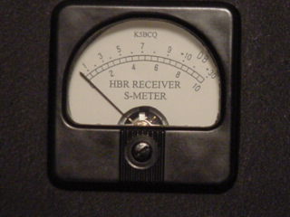 Custom S-Meter
If you really have some time, repaint it with black wrinkle paint to match the National dial.
General capacitor characteristics
Go To H&K IndexHere are a few hints on which type of capacitor to use in a specific circuit:
- Use disk ceramics for general bypass and coupling where exact value and thermal stability is not that important
- Use micas and silver micas in tuned circuits where stability is important
- Use mylars in audio sections
- Use temperature compensating caps for extreme stability but beware that it generally requires some experimentation to keep from over correcting and actually creating worse instability
- The new Polypropylene and Polyester caps are far superior to the old paper tubulars. All old paper caps will eventually fail. The number of times you will have to repair an old radio is directly proportional to the number of paper tubular caps you have not replaced.
- Always mount the caps with the "outer foil" end (indicated by band) toward ground for better shielding/safety
- Make certain the voltage rating is adequate for the application
- Generally, dipped caps are better to minimize moisture intrusion by sealing the capacitor.
Finding defective capacitors
Go To H&K Index
Before making any measurement make certain the capacitor is fully discharged.
Four things can generally happen with capacitors; they develop shorts or opens, they change value, or their leakage increases to unacceptable levels. Most capacitor applications will tolerate a wide range of values (coupling, bypass, filter) and some won't, like those used in tuned circuits.In order to measure values, you need a capacitor checker or bridge. These are generally available at swapfests (Heathkit, Knight, Eico, etc). Capacitor checkers generally provide a leakage test for electrolytics, and some also provide some level of leakage testing for the smaller capacitors. Capacitor checkers require that you remove the component from the circuit for testing and even good ones which perform "in circuit tests", usually perform a gross level of shorts test by applying a 10Khz or so signal to the component. Not real definitive but a good/quick pass/fail test.
You can also perform a quick shorts/opens test of capacitors by observing the "kick" of a VTVM/DVM (resistance measurement) as you connect it across the capacitor. It's best to compare to a "known good" capacitor of the same value.
When it's been determined the capacitor is not shorted or open and it's value is "close enough", we get to the more subtle failure mode, especially for the smaller capacitors......excessive leakage.
Testing small capacitors (Leakage measured in MICROamps):
For smaller (less than .01 mfd) coupling, bypass, and mica caps look for less than 0.1 microamp leakage on new capacitors and 0.5 microamp max on old ones. For capacitor values from .01 to 1 mfd look for less than 0.2 microamp leakage on new capacitors and 1 microamp max on old ones. Only 2 microamps coupling capacitor leakage across a 500K grid resistor, in tube equipment, will result in a 1 volt bias level change and the possible resultant signal clipping ........and they don't get better over time. You may elect to use different pass/fail criteria but "you get what you pay for".Testing for leakage at rated voltage is important. This is representative of some old paper caps recently tested: .006mfd 800V paper capacitor (not open/shorted, value "OK")
- At 10V the leakage was .4 microamp (not too bad)
- At 100V the leakage was 10 microamps
- At 200V the leakage was 27 microamps
- At 600V the leakage was 186 microamps
You need access to a good capacitor tester which will test insulation resistance (at rated voltage) up to, say 5000 Megohms (like the military ZM-11), or at least a good capacitor checker which has a "paper/mica" leakage test position which will test for 0.1 microamp and will also test at rated voltage. You can verify your capacitor checker sensitivity by measuring a high value resistor and observing the "eye" closure. Random sampling of two capacitor checkers on the 600VDC range showed the following current when the "eye" closed indicating leakage:
- 1.5 microamps minimum on an Eico 950
- 0.1 microamps minimum on a Heathkit IT-28
I have a ZM-11 military RLC bridge for very accurate measurements, but generally use a Heathkit IT-28 capacitor checker for the convenience (fast, easy to use, accurate enough). The only drawback is tube warmup time but this was offset by the $3 it cost at a swapmeet (minus cord and knobs).
Testing electrolytics (Leakage measured in MILLIamps):
Electrolytics have much higher acceptable leakage levels depending on the electrolytic and it's value.... a few milliamps is "OK" for power supply filter caps. For these use ONLY the voltage range technique on the VTVM/DVM because the initial current surge may be quite high. Leakage causes poor ripple filtering, heat, some loss of power and eventually total breakdown of the dielectric....something you want to avoid.Some people have suggested paralleling a "known good" electrolytic with a questionable one for testing. This, however, does nothing to remove the problem part and doubles the capacitance. If you have a leaky capacitor (passes DC current due to internal degradation/failure) it will still leak with another across it. You need to remove the defective capacitor.
Sprague uses the following formula for the limit of "good": I = kC + 0.3
I = the max leakage in milliamps, C is the capacitance in mfd
k = .02 for 101-250 WVDC
k = .035 for 251-350 WVDC
k = .04 for 351-500 WVDC
Aluminum electrolytics which have not been used for some time (in equipment or on the shelf), need to be "reformed". The need for reforming applies only to aluminum electrolytics and is the result of a characteristic of the electrolyte used. The electrolyte resistance drops over time with non-use (includes on-the-shelf and in the junkbox). Initially applying full voltage can cause excess current to flow, resulting in internal overheating and component failure (sometimes with sudden and nasty results as the capacitor ruptures). Power supply B+ voltages will also rise faster in circuits where the tube rectifier has been replaced with diodes. When first powering up equipment, SLOWLY increase the B+ voltage over a period of approx 5-10 minutes by using a Variac in the AC line or other means of stepping the input voltage (series light bulb, series resistors, etc). Individual electrolytics can be reformed and tested at the same time by using the electrolytic capacitor leakage test on a capacitor tester. Start low, stop when the eye closes, wait till it opens, step it up some more, etc., until you reach the capacitor rated working voltage. Be sure and discharge the capacitor when you are done.
Cleaning contact surfaces
Go To H&K IndexMany of the older parts (especially those stored in the garage) will develop intermittent contact points due to wear, oxidation, and debris. The results are "scratchy" potentiometers, intermittent switch contacts, intermittent tube socket pin contact, etc. One of the best solutions is to use DeoxIT D5 (made by CAIG Labs) which comes in a spray can with a small plastic tube to direct the spray. This stuff really works and is available from many of the electronics supply houses.
Cleaning chassis surfaces
Go To H&K IndexIf the radio was kept out in the chicken coop, chances are the chassis could use some cleaning. There are many cleaners available from the grocery store, some are better than others, some are not to be used on plastic, and there is advice everywhere ....from "Don't touch it" to "I ran it through the car wash first". A very effective cleaning method, involving some time and elbow grease, uses Windex, an old toothbrush, a clean, lint free cloth, and MANY Q-tips. Just keep at it until the surface looks clean and let it dry. Works surprisingly well. Don't forget trying plain old soap and water. Soap and water cleans up front panels very well and does not disturb lettering like some chemicals will.
Tube testers
Go To H&K IndexThe best "tube tester" is the specific circuit application environment where the tube is used. Since that requires "known good spares" for substitution and gets very complex if the tube count is high, there are several types of tube testers available.
The very smallest and cheapest "supposed tube testers" check only filament continuity which you can also do with an ohm meter. These testers have no value what-so-ever ....unless you cut the cord off and want to use it as a base for a desktop tube display and/or paper weight.
"Emission" testers (most of the Knight, Heathkit, Eico, etc. testers) connect a DC milliammeter in series with the plate, tie the screens and plate together, heat the cathode, and measure the current using a selectable AC plate voltage and load. The tube performs the rectification function. They don't use the control grid at all and therefore don't measure the tube Gm. Gm (or transconductance) is the ratio of plate current change to grid voltage change and is typically one of the tube manufacturer's specifications. These emission testers do as stated ...check cathode electron emission and will catch the majority of typical "weak tube" problems and internal shorts. Good availability and low cost make them very popular. They will not detect grid emissions problems, they can not be used to determine quantitatively how close the tube is to its specifications, they can not be used for tube matching, etc. All that said, it's still a good "quick, cheap, and close enough" tube tester. I built and used an old Knight 600 for many years.
"Dynamic Conductance" testers (Eico 666/667) supply the grid with adjustable AC, supply the plate and screen with adjustable AC (the tube performs the rectification function) and measure the resultant plate current with a DC milliammeter. The result is a combination of emissions and dynamic conductance which they call "Merit". Better and a little more costly than an "Emission" tester but not as good as a "Dynamic Transconductance" or "Dynamic Mutual Conductance" tester. They also measure for internal shorts.
The "Dynamic Transconductance" and "Dynamic Mutual Conductance" testers (all the Hickoks, TV-7s, Heathkit TT-1s, most B&Ks, etc) are more costly, but they measure the tube "mutual conductance" or "transconductance" (Gm). They more closely test to the operational environment by providing selectable -DC bias to the grid, selectable plate and screen +DC voltages and introduce an adjustable AC signal (the "dynamic" part) on the grid. These testers have an adjustable plate load and measure the change in plate current relative to the AC voltage on the grid with an AC milliammeter. They are excellent for determining tube quality and most allow direct reading of (or conversion to) tube Gm in micromhos. This is useful for comparison to the manufacturer's tube Gm specifications. They all measure for internal shorts.
There are outstanding "Dynamic Transconductance" tube testers for determining exact tube characteristics (TV-2, etc). These testers have literally everything metered simultaneously (6+ meters). However, they are complex, take longer to set up, and as a result, are more prone to "operator errors". They are generally quite expensive but look impressive. I personally believe the radio amateur doesn't really need this level of capability. Only get one of these if you really CAN program your VCR.
All tube testers provide testing for a "range" of tubes. A TV-7 will test any of the common older 4/5/6/7/8 pin tubes types (like 26, 30, 807, 811A, 1625, etc), octal tubes, loctal tubes, and the miniature tubes (as well as other types the military used...acorn tubes, pencil tubes, 829B, etc). The last tube data manual (that I know of) is dated January 1962. If you don't have the latest level, Antique Electronic Supply (AES) has them. A TV-7 will not test compactrons, used in some ham gear, and newer miniature tubes unless the test data for these tubes can be found. It will test everything in any HBR Receiver or Collins S-line. A B&K 747 (solid state tube tester....ironic, huh ?) will test octal tubes, loctal tubes, miniature tubes, and compactrons. It will not test the older 4/5/6/7/8 pin tube types. It will test everything in an HBR Receiver, Collins S-line, any Heathkit (including the compactrons), and any tubes in other ham equipment including imported units.
I finally found a very nice TV-7 which I use to test 4 & 5 pin tubes. However, the one I use most often because it's fast and has a very sensitive grid emissions/leakage test, is the B&K 747. The B&K has easy setup using "common" tube sockets and selection lever setup for the rest, has single control selection lever reset, and has two test buttons for dual section testing.
Tube testing
Go To H&K IndexMake certain your tube tester is calibrated per the manual. On simple "emission" testers this involves setting the filament voltage to the correct level so the "Line Test" indication on the meter is correct. The more complex calibration procedures involve setting bias levels, meter balancing, load calibration, leakage/shorts calibration, etc and are covered in the various tube manuals (SND Tube Sales and others offer copies of tube tester manuals).
The tester instructions are not kidding when they say the first test should be "shorts and opens". Tap the tube slightly to check for intermittant shorts and if the tube indicates a short, DO NOT TEST FURTHER. Depending on the type of short, you can damage the meter movement. I have personally seen many low emission tubes (not enough electron flow from the cathode to the anode), quite a few filament to cathode shorts (very common failure), several grid emissions failures (grid saturated with, and re-emitting, electrons from the cathode), some gas failures (secondary emissions as the electron flow strikes unwanted internal gas molecules knocking electrons off and making the ions pull electrons off the grid), and every now and then, an open filament or cracked tube glass. The "gassy" tubes and those with "grid emissions" (see above) cause a level of grid current to flow in the oposite direction, changing the grid bias, and possibly resulting in waveform distortion/clipping. The effect would be similiar to the grid bias change due to a leaky coupling capacitor from the previous stage.
Micromho meter indications (Gm) are useful to compare to tube manufacturer specifications if you really want to "get it right". Generally "good/bad" scales are more than sufficient and will show 60%-120% of spec to be "good", a small 10% "?" ..probably OK but should be replaced, and 0-50% of spec for "bad" or "low emissions". The "low emissions" tubes will still work but are marginal and should be replaced. You can increase the filament voltage slightly to increase the emissions (thats how "picture tube brighteners" worked) but it's generally not worth it. Maybe in the year 2100.
Crystals
Go To H&K IndexFT-243 style crystals that quit working in HBR receivers (indicated by suddenly no audio and no S-meter reading) or have low output (indicated by weak signals) may be improved by cleaning the internal contact surfaces. Remove the 3 screws and carefully disassemble the crystal. Clean the metal contact points with a pencil eraser and then clean everything with alcohol and allow to dry. Reassemble with the ridges on the metal plates toward the crystal. Keep the cat off the desk while you are doing this.
Hermetically sealed crystals are generally more "active" and stable than the FT-243 types, so you might consider them. If you have a FT-243 socket, solder the pins from an old discarded octal tube to the crystal wires/pins and plug it in.
The 3500Khz crystal calibrator is quite useful for alignment but sometimes a frequency of 3500Khz is not the most convenient since it's at the edge of the band. The advantage of using a 3500Khz crystal (according to Ted Crosby) is that it will require a lower harmonic and therefore the signal will be cleaner and stronger. Ted was not without strong opinions. The advantage of a 100Khz crystal is several marker points across a given band and IF alignment if you happen to use 100Khz IFs. If you can't find a 100Khz crystal, 200Khz FT-241 crystals are quite common and readily available from surplus stores like Fair Radio (see "parts sources" below). Or try 250Khz and 500Khz crystals in the calibrator.
The 2nd Osc crystal (1700Khz +/-10Khz) is just something which you have to find at swapfests, surplus stores, junk boxes, etc. No "substitutskys" here. I think you can actually go somewhat higher than 1710Khz ...maybe up to about 1745Khz without "birdie" or ham band conflicts. Try it if you have one. I've even used a common 1.8432Mhz crystal, works great for bringing in signals, but one heck of a "birdie" at 3.6864 and other multiples and some other unwanted mixer products (more "birdies").
Use of ceramic sockets
Go To H&K IndexA few comments by Sandy (W5TVW) on the use of ceramic sockets (Note that this was written in reference to a regen receiver, but the same applies to the HBR frontend....RF, coils, and Osc):
Quite a few of the "old books" emphasize the use of ceramic/isolantite/porcelain/steatite etc. tube and coil sockets for best performance. Being something of a "hard head" about some things, I have sometimes ignored this warning.......to my detriment! I have steered clear of the cheap phenolic "wafer" sockets simply because they are cheap looking and flimsy. I have used the Amphenol black Bakelite sockets however. My advice is: DON'T ! I have also used the light brown molded "mica filled Bakelite" sockets as well. These have, for the most part, "worked out", but from now on, I intend to heed the advice of the old timers and use nothing but a ceramic type socket for both the plug-in detector coils and the detector tube.
I have had some very remarkable results from "one tubers" using ceramic sockets, only to have failure, or at least partial failure, using something inferior to ceramic in the SAME CIRCUITS THAT WORKED SO WELL before! The old guys might not have been insulation experts, but they knew what they were about here.
Making coil forms
Go To H&K IndexConrad (W7WLM) uses PVC all the time for both receiver and transmitter coil forms which he says works fine. If you get the right size, it will fit the notch in the flange around phenolic octal tube bases that are used with metal tubes. It can be effectively epoxied to these tube bases if it is clean and oil free. Use the General Purpose Epoxy, available at hardware store which is solid in the twin syringe pack, not epoxy designed for use in repairing ceramic or glass.
There has been a lot of criticism of PVC in Amateur literature with regard to its losses at RF frequencies and a lot of people don't use it for this reason. PVC works just fine and does not exhibit any rf heating tendencies up to well over 50 Mhz - even at fairly high power setting.
For most purposes, a coil form three inches long is satisfactory, unless you are winding coils for 160 Meters, which requires a coil form about four inches long. Another approach is to make the coil forms longer, about 4 1/2 inches long, and simply cut them off to the desired length AFTER you have wound the coil on the form. Start at the bottom and wind toward the top.
He sprays each completed coil, on the form, with Krylon Clear Plastic Spray, as each individual coil is wound and its free end soldered into the desired pin. When finished, this whole process produces a very nice looking coil which could pass for a commercially manufactured coil.
After the coil is completely wound, soldered and sprayed, He marks the coil, around the upper space beyond the upper winding, with the use of the coil, it's frequency range and he marks each winding, adjacent to the winding with the number of turns of wire in the winding and the wire size, so that later, you have this information. If you use fine point black Magic Markers for this, it is wise to do this marking AFTER you have placed any final coat of plastic spray or enamel on the coil form, since virtually all of these finishes are solvent for the marker.
Another approach is the use of the Amphenol plugs with are mounted through a keyed hole and retained by a circular spring clip. These plugs, while rather expensive are still available from Newark Electronics, Allied Radio, and swapmeets. They are available in 4, 5 and octal pin sizes. If you have access to a lathe, you can use a size of PVC pipe that is thick enough to machine a groove in one end which enables them to be slipped over the chassis side of these plugs and epoxied in place. Along these lines, Jeff (K4ZKU) has built some nice coil forms using old tube bases. He used bases from old 807's, cut the base down on his lathe and used a PVC thin wall bathroom sink drain tubing kit which is enough for several coils. He epoxied the cut down base from the 807 inside the PVC tubing, cut the tube off to about 3", then cut the larger enclosed tubing in the kit, to about 1/2 inch slices to put at the top to hold the APC cap. Use PVC glue here.
Some have suggested using old plastic pill bottles which is OK if they are sturdy so the coil wiring turns don't move. Recently some testing has shown that coils wound on those amber pill bottles have just has high a "Q" as those wound on the Amphenol 5-pin forms. PVC is the same way. What does affect "Q" is the material you use to coat the windings. Here is an example of coils wound with #28 AWG magnet wire:
| "Q" at 6 Mhz with all coils measuring 20.5uH (cap 35pf): | |||||
|---|---|---|---|---|---|
| Reference | Note 1 | Note 2 | Note 3 | note 4 | |
| 1-1/4" Amphenol 5-pin | 175 | -- | 175 | -- | |
| 1-1/4" amber pill bottle | 180 | -- | 177 | 172 | |
| 1-1/2" amber pill bottle | 161 | 147 | -- | -- | |
| 1-1/4" untreated cardboard | 152 | 130 | -- | -- | |
| 1-1/4" PVC | 173 | -- | 175 | -- |
Notes:
- Plain wiring, no adhesives, no tape to hold windings
- Use a light coat of clear fingernail polish to hold windings (strips across windings didn't work), Q reading 15-20 points lower when first applied, above readings are after 48 hours.
- Use Elmer's Stix-All silicone to hold windings (4 strips across coil windings)
- Use Scotch black electrical tape to hold coil windings (1-1/2 turn)
Coil repair
Go To H&K IndexWhen working on an older HBR with stability problems, check the solder joints on the coil pins and resolder if required. Some that "look good" and "ohm out good" may not "be good". When you find bad or questionable solder joints, it's best to remove the old solder before resoldering, don't just add more solder (like I did).
From Tom (WA0EAJ); for coils which have DUCO cement holding the APC caps in, and if the cement is old - refresh the cement with some clear finger-nail polish ... works like a champ, and reminds you of your Mother. Don't use the finger-nail polish to hold wire turns in place (see above).
Coil winding
Go To H&K Index
A few points from Bob (W4RLC) on coil adjustment and the effect of moving
the tap: After setting the bandset trimmer in the coil I was able to setup
the front end for 40 meters. The receiver had fairly even gain across the
frequency coverage. But the desired range was not what I wanted. The receiver
tuned from 7.00 to 7.60 MHz. I tried adjusting the coil below the tap to get
it to provide the correct frequency coverage. That did not work so I moved
the tap down 3 turns. Now the receiver tuned from 7.00 to 7.140 MHz. I moved
the tap to 2 turns from the original point. Tuning range was now 7.00 to
7.240 MHz. OK, so I move it 1 turn from the original tap point and the
receiver tunes from 7.00 to 7.336 MHz. This range is just fine with me.
Coil holders
Go To H&K IndexFor a cheap coil holder, use a Styrofoam block or a piece of wood drilled to hold the coils in place. Or you can build a coil cabinet. See various attached picture files for details.
A few notes on IF transformers
Go To H&K IndexI've seen several older IF transformers on older rigs which won't tune up properly. Could be any combination of coil/padder/slug or mechanical changes over time. Sometimes the IFs which had the fixed mica capacitor moulded into the base deteriorate over time due to corrosion and change value (they also develop shorts). Sometimes the slug breaks or cracks....or this happened before and someone replaced the slug with "a handy one in the junkbox". Replacing the fixed capacitor (maybe a slightly different value) to get the IF to tune up properly may be the solution. By the way, the correct position for the slugs in an IF is toward the outside of the transformer (since there are typically two peaks for each slug). Tuning the slugs towards the inside can overcouple and widen the IF passband. Capacitor trimmer tuned IFs, of course, don't have this problem even though any rotary trimmer also has two peaks. Mica compression trimmers only have one peak and therefore don't have this problem at all .....they have other problems like shorting after the mica deteriorates.
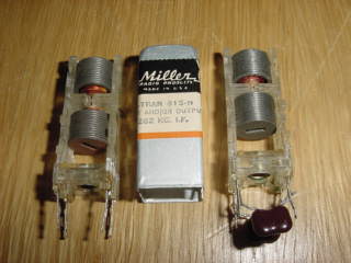
From the JW Miller catalog: 612 Series IF transformers are iron core transformers which offer better gain and selectivity, due to their higher Q, than comparable air core transformers like the JW Miller 512 Series. An even more stable, permeability tuned, iron core IF transformer is available in the JW Miller 912 Series. I'm sure there are later miniature size IF transformer equivalents but don't have the specs for the JW Miller 1710, 1709, etc.
Each series has several types (input, interstage, full-wave, half-wave) and frequency ranges (127-137Khz, 450-550Khz, 500-550Khz, 1400-1600Khz, etc). The "input" type (number ends in "1"...for example: 612-M1) has optimized coupling for maximum gain and selectivity. The "interstage" type (number ends in "2") has it's coupling adjusted to slightly more than optimum which results in a slightly wider bandpass. The "half-wave" and "full-wave" types (number ends in "3" or "4" are overcoupled. The 612-M1 ("input" IF transformer, 127-137Khz) was selected for the HBR-16 design because of overall selectivity. It's also padded down to a center frequency of 100Khz from the original 132Khz to further increase selectivity.
This section provides some measurements on individual (loose) IF transformers. The transformers were peaked at their center frequency with fixture/leads attached to properly compensate for the additional capacitance. Impedance matching was done in the fixture using: a 50 ohm termination on the Tracking Generator, a toroid transformer with a 1:20 Voltage ratio which translates to a 1:400 impedance ratio or 20k ohms for the IF input and a 1Meg resistor for the IF output load. The shield can was grounded.
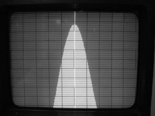
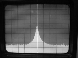
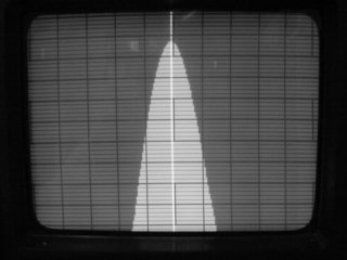
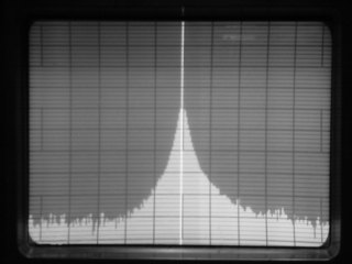
The first conclusion drawn is that the data looks "reasonable". There is not a great abundance of these parts, so the sample size is small (one of each). The BC-453 IF specifications look really good and as you can see from the pictures (with the rod "OUT") the BW can be narrowed to 3.0Khz. With the rod "IN" the transformer is over coupled as shown by the "dual humps" and the BW increases to 5.4Khz. Results in the middle of this range can be achieved by positioning the rod between the two detents. Really nice capability.
Since what you are after for a SSB/AM passband is a relatively "flat"
top and "vertical" sides, you can see that some experimentation in stagger
tuning the IFs might provide better overall SSB/AM receiver performance. The
really narrow, "flat" top, and "vertical" side SSB passband can usually only
be realized with mechanical/crystal filters although multiple IFs in series
with the appropriate amplifiers will provide some improvement. A passband
which is highly peaked (as with a Q-multiplier) is great for CW reception.
| IF Transformer | Center Freq | BW -6dB | BW -20dB | BW -40dB | Notes |
|---|---|---|---|---|---|
| JW Miller 1709 IF | 100Khz | 2.5Khz | --- | --- | (2) |
| JW Miller 1709 IF | 100Khz | 5.7Khz | --- | --- | (3) |
| JW Miller 1710 IF | 100Khz | 3.0Khz | 8.2Khz | --- | (13) |
| K-Tran IF (modified) | 100Khz | 3.3Khz | 10Khz | --- | (11) |
| K-Tran IF (modified) | 100Khz | 2.3Khz | 7.2Khz | --- | (14) |
| JW Miller 612-M1 IF | 132Khz | 5.9Khz | 20.5Khz | --- | --- |
| BC-453 IF (#12012) | 85Khz | 3.0Khz | 10.0Khz | 26.0Khz | (4)(6) |
| BC-453 IF (#12012) | 85Khz | 5.4Khz | 14.0Khz | --- | (5)(6) |
| two BC-453 IFs (#12012) | 85Khz | 1.8Khz | 4.3Khz | 11.0Khz | (8) |
| two BC-453 IFs (#12012) | 85Khz | 3.6Khz | 7.5Khz | 15Khz | (9) |
| Homebrew 1600 IF #1 | 1600Khz | 36Khz | --- | --- | (7) |
| Homebrew 1600 IF #2 | 1600Khz | 43Khz | 190Khz | --- | (7) |
| K-Tran IF (modified) | 1610Khz | 26Khz | 75Khz | --- | (12) |
| JW Miller 1730 IF | 1800Khz | 36Khz | --- | --- | --- |
| BC-454 IF (#7274) | 1600Khz | 33Khz | 85Khz | --- | (10) |
| K-Tran IF | 262Khz | 10.7Khz | --- | --- | (1) |
| K-Tran IF | 455Khz | 21.0Khz | --- | --- | (1) |
NOTES:
- The K-Tran replacement IF transformers are off the shelf units and were added for comparison purposes.
- Data shown is per IF specifications. The 1709 has less attenuation (insertion loss) than the 1710 and maybe they use higher "Q" coils.
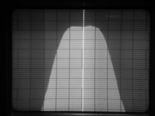
- This is an example of what happens when the IF transformer is improperly peaked. Each slug tuned IF coil has two peaks (one toward the inside of the IF and one toward the outside of the IF). Toward the outside for both IF transformer coils is correct. This shows what happens when one of the slugs is peaked toward the inside of it's coil and the coupling to the other coil is increased through the slugs.
- With the Micarda rod "OUT". BC 453 IF coils have a "Q" of about 50.
- With the Micarda rod "IN" (over coupled)
- One of the BC-453 IF trimmer caps was modified so both trimmers are across the fixed padder capacitors.
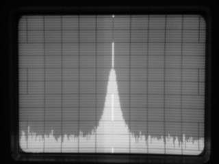
- This demonstrates some variation of the homemade, link coupled, 1600 Khz IFs found in two HBR-16s. I'm surprised they are that close, it's "a little" wide, but a nice looking passband.
- With both Micarda rods "OUT" (not overcoupled) ....very sharp for SSB
- With both Micarda rods "IN" (overcoupled) to "flatten" the passband
- These are 1415Khz IFs padded to 1600Khz by replacing the button capacitors with 120-140pf mica capacitors.
- An excellent 3/4" square 100Khz IF can be easily made from one of the K-Tran 262Khz IF transformers. In this case JW Miller 15-H IFs were used. One coil is modified by moving it to the end of the form (see section below on Substitute IF Transformers). Adjust the coils to resonance with a 430pf padder capacitor added to both windings for 100Khz.
- A 3/4" square 1610Khz IF can be made from a slug tuned K-Tran 455Khz IF by replacing the coils with 100 turns of 5/44 Litz wire or 90 turns made up of 2 strands of #40 AWG spaced 5/8" apart.
- The 1710 is wound using bifilar (2 strands of) #42 AWG wire and the coils are separated by 1/2" on a 1/4" form. Diameter of the coil is 15/32", height is 5/32", inductance at 100Khz is approximately 6.4mH, and measured "Q" is 70. The resonating capacitor is approximately 333pf. Fun to try and make some. See the "Coil Winder" section via K5BCQ's Homepage
- This is what happens if both coils are moved to the ends of the coil form.
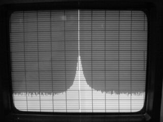
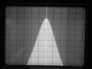
JW Miller #1710 IF (left is 1dB/1Khz, right is 10dB/10Khz)
Modified 262Khz K-Tran IF ...both coils moved (left is 1dB/1Khz, right is 10dB/10Khz)

JW Miller 612-M1 IF (div 1dB/1Khz)
BC-453 IF with rod "IN" (div 1dB/1Khz)
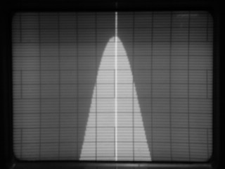
BC-453 IF with rod "OUT" (left is 1dB/1Khz, right is 10dB/10Khz)
Two BC-453 IFs with rod "IN" (div 10dB/10Khz)
Homebrew 1600Khz IF 36Khz BW (div 1dB/10Khz)
Substitute 100Khz IF Transformers
Go To H&K IndexI hear about a lack of "critical" IF transformers for homebrew projects and maybe we will need to "wind our own". There is some difficulty finding exact parts as specified in the 1960 articles when these transformers were plentiful. However, from what I've seen at swapmeets, there is no need to "wind your own". It's much easier to do a "make from" than "make one".
Use BC-453 85Khz IF transformers (some other military receivers also have 85Khz IFs) as a substitute for the larger 100Khz J.W. Miller IF transformers used in the HBR-16 or receivers with chassis space. These transformers can be used as 85Khz IFs as-is or change the pad capacitor to a smaller value to move it to 100KHz. At the last swapmeet I saw a badly dented "parts only" BC-453 with all the 85Khz IF cans, variable cap, coils, dial mechanism, etc intact for $7.00. Seems reasonable to me. Several people have used these transformers with excellent success, it's really a good, high quality IF transformer.
(some IFs could be switched during later maintenance)
| Characteristic | R23 | R-23A | BC-453A | BC-453B | R-11A | |
|---|---|---|---|---|---|---|
| 1st IF number (coils not tapped) | 4698 | 10786 | 4698 | 4698 | 12011 | |
| 2nd IF number (coils tapped) | 9641 | 10790 | 7267 | 7267 | 12012 | |
| 3rd IF number (coils tapped) | 9642 | 10791 | 4677 | 9642 | 120?? | |
| --connector | (3) | (3) | (3) | (3) | (4) |
Notes:
- All these IFs have the input trimmer to ground and the output trimmer across the output coil. The larger value, fixed padder capacitors are across both the input and output coils. This is different from other ARC-5 IFs ...BC-454, etc.
- The DC resistance of ALL transformer coils measure approx 123-143 ohms. Those without taps measure approx 123-143 ohms across the input/output, those using taps measure approx 34-43 ohms across the input/output. Tapped (2nd and 3rd) IFs can be readily changed to "input type" 1st IFs with the transformer input/output across the entire coil. The purpose of the taps is for impedance matching and to reduce overall gain.
- Plug-in Mica connector with bananna jacks.
- Ceramic connector with round solder pins.
- ALL 85Khz IFs have adjustable coupling between the coils. With the Micarda rod "IN" you have an overcoupled transformer with a wider Bandwidth (5.4Khz at -6dB). With the Micarda rod "OUT" you have less coupling and a sharper Bandwidth (3.0Khz at -6dB).
Excellent substitutes for the smaller 3/4" 100Khz IF transformers, used in the HBR-11/12/13, can be made from one of the K-Tran 262Khz IF transformers. In this case JW Miller 15-H IFs were used. The K-Tran units with the cup tuning vs slug adjustment seem to have a greater permeability and a wider adjustment range. For 100Khz, add 430pf padder capacitors to the internal (90pf) capacitors. The coils, when tuned for the high inductance required at 100Khz, will be overcoupled (wider BW). A solution which maintains the high inductance, yet moves the coils further apart, is to heat the upper (easy access) coil until the wax melts and slide it to the end of the coil form (may have to disconnect/reroute the wires). The characteristics are very close to those of the JW Miller #1710 IF transformer. Slightly better characteristics can be obtained by moving both coils to the ends of the coil form, however, the bottom coil is more difficult to heat/move.
Modifying 3/4" 455Khz transformers does not work. The slug tuned forms require substantially more inductance and even with a pretty good coil winder and using 2 strands of #42 AWG wire, the coil will be too large to maintain adequate spacing between the coil and the can. The can will also reduce the inductance some, due to capacitive coupling. The tight, one wire adjacent to another, factory made windings, are mandatory. The cup tuned, self shielding, K-Tran forms don't allow enough room inside the cup to add windings and stacking two coils, which will fit, still does not provide enough inductance. Litz wire takes up too much physical space on small/dense coils like this. Although two-strand/bifilar is better, there is not enough space using any coil winder I have access to. Only the 262Khz K-Tran coils with tuning cups, can provide enough inductance.
Before and after 262Khz to 100Khz K-Tran IFs ....relatively simple modification, see above
Substitute 1610Khz IF Transformers
Go To H&K IndexFor 1610Khz coils, Darrell (WA5VGO) has the following suggestions:
You might be fortunate enough to find NOS Miller coils, but the chances are pretty slim. I'm sure the 100 kc I.F. transformers are more common. These 1610 kc coils are not critical and are surprisingly easy to build.
The inductance of the high impedance side of the coils needs to be about 135uH. I had some NOS slug tuned coils that I think were probably for a television set. They had far more inductance than necessary. The forms were 1 -1/2" long and 3/8" in diameter. I just kept peeling away wire until I could get the coil to tune from about 85 to 150 uH. If you are winding the entire coil I would suggest about # 36 wire. The low impedance side is 5 turns spaced 1/2" from the other winding. I used #22 wire, but that's probably on the heavy side. #24 or #26 might be a better choice.
That's all there is to it. It's not difficult, especially if you start out with existing coils like I did. These coils are used as coupling devices and are not critical to the over all performance of the receiver. By the way, another possibility would be to get some 1650 kc IF transformers from an old CB radio, strip off one of the windings and add the link coupling. I have substituted these coils into a working HBR that has the proper coils and there was no detectable difference.
An excellent 3/4" square 1610Khz IF can be made from a slug tuned K-Tran 455Khz IF. Remove the windings, replace them with 100 turns of 5/44 Litz wire, space the coils 5/8" apart, and use the internal 90pf resonating capacitors. Coil "Q" is 125 and inductance is 125uH (outside the can) ...OR... use the wire removed from the 455Khz coils if it's high "Q" (in this case 2 strands of #40 AWG). Use 90 turns of 2 strands of #40 AWG, space the coils 5/8" apart, and use the internal 90pf resonating capacitors. Coil "Q" is 110 and inductance is 125uH. The Litz wire coil will be more bulky than the densely wound coil using 2/40 wire. Other variations such as removing turns off a 455Khz IF (slug or cup tuned), removing one coil completely and using link coupling to the second inductor, using solid wire for the coil, etc will work ...but the -6dB BW was around 50Khz for the ones I tried. "Sliding" the 455Khz coils 5/8" apart didn't work (inside wire breaks).

Before and after 455Khz to 1610Khz K-Tran IFs
Back in the early 60s there were not that many stations around 1610Khz but today there are many strong 1600Khz Broadcast stations in the area. If you have a problem with one, try better shielding or move the 1st IF to a higher frequency and adjust accordingly.
Repairing IF Transformers
Go To H&K IndexIf you happen to have a defective IF transformer (open/short) all is not lost. Carefully remove the aluminum can and examine the wiring closely for breaks under a magnifier. If it's an obvious break/short at the pin, it's easy to repair with some carefull soldering. If it's in the coil, you may still be able to repair it. Very carefully scrape a bit of insulation off the coil in various places with an x-acto blade attached to an ohm meter to determine the location of the break. The last one I found was at the inside, so I picked a turn loose at the core and ran a wire from there to the IF transformer solder pin. Works great, required only a small adjustment to retune and is one heck of a lot easier than rewinding the coil or finding an exact replacement.
Checking IF Transformers
Go To H&K IndexFrom Conrad (W7WLM): I discovered that it is a good thing to test and pre-tune all IF cans BEFORE they are installed into the receiver and wired in. This can save you lots of headaches, especially if there is something wrong with any of the IF cans. All that is required to do this is a signal generator that will reach the IF frequency and provide an audible tone on the test carrier. This generator is connected across the Primary of the IF can. Then, some form of high impedance detector, one equipped with at least a headset audio amplifier, is connected to the output of the IF transformer. The transformer is then peaked for maximum through-put. No attempt is made at this time to stagger tune the IF transformer resonant circuits. This can be done later, during the final receiver IF amplifier alignment procedure.
What this pre-tuning procedure accomplishes is:
- Demonstrates that the transformer is a good and useable part.
- All the IF cans that you have chosen have the same operating frequency.
- By pre-tuning the IF cans, the receiver will work well enough after final assembly for the builder to know that he has done good work.
J.W. Miller BFO Coil
Go To H&K IndexHBR-16 Receivers using the 012-M5 and 612-M5 BFO coils need to be sure they are tuned to 100Khz. Checking it with a frequency counter or scope is best. Just like the IF transformers are padded down from 127-137Khz to a center frequency of 100Khz by adding 50pf SM capacitors, some BFO coils can not be adjusted down to 100Khz without first adding a 100pf SM capacitor across the whole BFO coil. When adjusting the BFO, it is quite easy to assume that the strongest heterodyne you hear (really a BFO harmonic beating against the 2nd Osc.) is the correct "BFO signal" but poor BFO injection will occur at the Product Detector and SSB will be very difficult to copy (CW will be OK). This probability will be increased if you don't have all three BFO leads (signal, B+, and filament) shielded to provide signal isolation.
Adding a mode select switch eliminates the need for a BFO pitch control (can eliminate the BFO on/off switch and AM/SSB switch with extra switch contacts/positions) and adds to receiver convenience. Tune the main BFO to 99.2Khz for CW and the two added sideband selection trimmers to 98.4Khz and 101.6Khz (for a 100Khz IF receiver).
J.W. Miller tuning capacitors
Go To H&K IndexThere are two J.W. Miller 1461 capacitors; a 5 plate #1461 and a seven plate #1461-BS. The data in the HBR-16 October 1959 QST article are for the #1461. There are slight differences if using the 1461-BS (seven plate version). to allow proper dial tracking. See Picture/Data Links section for J.W. Miller scanned data sheets.
Substitute tuning capacitor
Go To H&K IndexCan't find the 1461-BS tuning cap ? What you have to keep in mind is that you are looking for a "3 section 5-23pf tuning capacitor" like those typically used for FM tuning. The military surplus places (Fair Radio, etc....see various sources/links, below) have many types of capacitors available from military FM gear. You can remove plates or increase spacing to reduce capacitance of larger value air variable capacitors, but it's much better to locate the correct value variable. Check out old junk FM receivers for these parts. Darrell (WA5VGO) has used the capacitors available from BG Micro with success but I'm told BG Micro has recently sold out of them.
Tuning dial mechanisms
Go To H&K IndexThe dial mechanism is one of the most important parts of a receiver and will often make or break the longterm usefulness of any homebrew receiver. Excellent electrical selectivity and sensitivity can be quickly overshadowed by poor mechanical accuracy, backlash, or a tuning rate which is too fast. A "good" receiver which is a pleasure to tune makes it a "useful" receiver. I personally believe that many homebrew receivers are "shelved" because not enough attention was focused on the tuning/dial mechanisms ....after all, this is where you spend the majority of your time when the receiver is in use.
A quick rule of thumb for dial mechanisms is: ball bearings are better than bushings, anti-backlash gears (ARC-5, BC-221, R-390) are better than ANY verniers, ball drive verniers (Jackson Bros.) are smoother and require less torque than pinch wheel drive verniers (National velvet-vernier), flywheels and weighted knobs enhance a smooth tuning "feel", dial cords stretch with load, so should be used for pointers only, and double set screws are more stable than single set screws.
Numerous alternatives for a dial mechanism are given below.
- EDDYSTONE 898.... "slide rule" dial, assumed by many to be the best, look great, are gear driven using spring loaded anti-backlash gears, have a 110:1 tuning ratio (55 turns stop-to-stop), and use smooth flywheel tuning. They measure 9-3/16" x 5-3/4" and will require additional depth behind the panel for the flywheel. The pointer has a horizontal travel of 7". A circular vernier scale, marked with 100 divisions, rotates 5 times for one traverse of the pointer. The sliderule dial comes with 5 lines for calibration markings and the vernier dial has a cam adjustment for correct zero setting. These dials were undoubtedly designed for Band "A", Band "B", etc shortwave coverage (like on the Eddystone SW receivers of that period) and 55 turns stop-to-stop is great. When used as an amateur band only dial (less than 500KHz per "band" except 10m), 55 turns is a lot of cranking ....the flywheel comes in handy. 898's cost a whopping $22.00 in 1966 and are somewhat difficult to locate today (and expensive).
- EDDYSTONE 598.... "180 degree arc" dials have a raised front bezel like the National ICN dials. They have a ball bearing drive mechanism, free from backlash and binding, with a 10:1 tuning ratio (5 turns stop-to-stop). They measure 6" x 4-1/2". The scale (5" diameter) is marked with 100 divisions over 180 degrees and has 5 lines for calibration markings. Unit can be readily modified for backlighting. 598's cost $9.00 in 1966 and are really difficult to locate, but I believe that is largely due to being less popular that the Eddystone 898.
- NATIONAL ACN.... "180 degree arc" dials have the Velvet-Vernier drive, a 5:1 tuning ratio (2.5 turns stop-to-stop), and measure 7-1/4" x 5". The scale (5-3/4" diameter) is marked with 100 divisions over 180 degrees and has 5 lines for calibration markings. The ACN front bezel is flat. Velvet-Vernier drives use pinch rollers and are relatively smooth and backlash free, but do require more torque than some other drive mechanisms. A 5:1 tuning rate is a little fast (my opinion).
- NATIONAL ICN.... "180 degree arc" dials with the Velvet-Vernier drive have a 5:1 tuning ratio (2.5 turns stop-to-stop) and measure 7-1/4" x 5-1/8". The ICN has a raised front bezel and dual lamp hardware for backlighting. The scale (5-3/4" diameter) is marked with 100 divisions over 180 degrees and has 5 lines for calibration markings. Dial mechanism is the same as the ACN unit.
- NATIONAL SCN.... "180 degree arc" dials with the Velvet-Vernier drive have a 5:1 tuning ratio (2.5 turns stop-to-stop), and measure 6-1/4" x 4-1/2". The SCN front bezel is flat. These are the dials shown in the HBR-14 and HBR-16 QST articles by Ted Crosby (...and they used to cost $3.00).
- NATIONAL MCN.... is the smallest National "180 degree arc" dial with Velvet-Vernier drive, 5:1 tuning ratio (2.5 turns stop-to-stop), and measure 3-7/8" x 2-1/4". The MCN front bezel is flat like the ACN and SCN.
- JW MILLER MODEL MD-4.... "180 degree arc" vernier drive dials have a 6:1 ratio and 36:1 fine tuning ratio over any 6 division portion of the scale. Dial measures 4-7/8" x 3-3/4".
- National RF Inc. model NPD-1..... "180 degree arc" vernier drive dials have a 6:1 tuning ratio and measure 2-3/4" x 3-3/4". This is a new, recently announced dial.
- National RF Inc. model NPD-2..... "180 degree arc" vernier drive dials have a 6:1 tuning ratio and measure 3-5/8" x 5-1/2". This is a new, recently announced dial.
- National RF Inc. model NPD-3..... "180 degree arc" vernier drive dials have a 8:1 tuning ratio and measure 3-5/8" x 5-1/2". This is a new, recently announced dial.
- JAMES MILLEN TYPE 10035.... panel dials are large 8-1/2" x 6-1/2" "slide rule" dials with a 12:1 tuning ratio. They use a dial cord/string for the pointer with a pinch roller vernier for the tuning capacitor drive and are very smooth. The front bezel is raised and the dials come with backlighting hardware. Replacing the pinch roller with some anti-backlash gears and adding a weighted knob would make this a very nice (large) dial.
- JAMES MILLEN TYPE 10037.... panel dials are "no string" drives with a 11:1 tuning ratio and are smaller in height than the 10035. I'm not exactly sure how these work since I've only seen a picture, but it looks like a pinch roller vernier drive with gear teeth on the outside, driving a cog/spiral strip with the pointer attached to it. These dials also come with a raised bezel and backlighting hardware.
- JAMES MILLEN TYPE 10039.... dials are a smaller, "180 degree arc" dial which measures 4" x 3-1/4" and has a 8:1 tuning ratio (4 turns stop-to-stop).
- NATIONAL NPW-O.... gear dial drives are very nice with the input and output shafts "in line" and perpendicular to the front panel. The dial readout is 0-500 in "1 unit" increments. It has anti-backlash gears and a very smooth mechanism. Tuning ratio is 20:1 (10 turns stop-to-stop). Excellent, if you can set the coils/tuning capacitor up to tune a 0-500Khz range.
- HOMEBREW ALTERNATIVE #1.... for a backlit "slide rule" dial is to build your own dial like Bob (WB4MNF) has done. See pictures for more detail.
- HOMEBREW ALTERNATIVE #2.... make a backlit 7" slide rule dial of your design, use two stacked Jackson Bros ball vernier drives on the tuning capacitor and attach a dial cord pulley to the input shaft of the second drive. 180 degree motion of the tuning capacitor requires 3 turns of the rear drive input shaft (18 turns of the front drive input shaft). If you use a 3/4" pulley you get 7" of dial cord travel. Many old Heathkits have 3/4" (and 1") pulleys. Heck of a lot cheaper than an Eddystone 898.
- BC-221 TUNING MECHANISMS.... are another possibility to use. These mechanisms are ultra smooth, have anti-backlash gears, and have a 100:1 tuning ratio (50 turns stop-to-stop). Note that the shaft drive is at right angles. The "on edge" dial (capacitor shaft) reads 0-50 increments and the "crank" dial divides that further (one revolution = 1 increment on the capacitor shaft). Sounds like a possible 0-500Khz dial to me, if the tuning cap/coil combination can be adjusted to be that linear.
- ARC-5 TUNING MECHANISMS.... from "parts only" ARC-5 Command Sets with anti-backlash gears (as was done on several receiver construction articles in the 50s/60s). Don't sell these readily available and cheap drives short. They are excellent for stability, no backlash, and great ball bearings throughout (same applies to the BC-221). Or just get some anti-backlash gears (most military units have them) and build up your own dial mechanism.
- A DIGITAL READOUT.... dial using the Oscillator, BFO, and IF frequencies as input, is another possibility. This might be an alternative if eyesight is a problem.
Tuning dial improvement
Go To H&K Index
The tuning rate for HBR "Amateur band only" SSB and CW reception is personal preference ....but a ratio around 10:1-30:1 seems best. 5:1 is too fast, 6.5:1 is marginally acceptable, 8:1 is good, and 110:1 is too slow. The torque required for some National Velvet-Vernier dials (and other verniers using pinch rollers) is high (stiff tuning).
- The HBR-11/12 articles recommend adding a Jackson Brothers, 6.5:1 ratio, Vernier drive to the existing tuning knob and attach it to the front panel with a bracket using the dial mounting screws. This would give a tuning ratio of 32.5:1. Any play in that bracket will affect tuning accuracy and "feel".
- Norm (WA5HPJ) has improved on the above and added a 2-speed dial mechanism (similiar to that used on Swan transceivers) by stacking two Jackson Brothers drives. The NC dial cover is removed and the second Jackson drive is anchored to the dial cover. The first drive (replacing the original National vernier) extends out so that the pointer can be attached to it and tracks the variable tuning capacitor. The metal knob is a Cannon plug cap. It is attached in place of the pointer on the outer drive and hides the second Jackson vernier. This also provides the 2-speed function.
- You can very easily modify the National ICN/ACN dials (maybe the others also) for much more solid and smoother tuning and with a 30% better rate by installing a Jackson Brothers Vernier drive. Remove the National "Velvet Vernier" drive (drill out the 4 rivits). Use a chassis punch to cut a 1-1/8" hole in the rear aluminum plate of the dial and the receiver front panel. Install a Jackson Brothers 6.5:1 Vernier drive in the hole using the two mounting ears on the drive (fits exactly). Use a soldering iron to heat and straighten out the bends of the ICN/ACN pointer slightly (don't touch the plastic with the iron). The ICN/ACN pointer bolts right up to new drive. Reassemble the dial and cut the shaft off to fit the knob. You can use the original National knob by drilling the insert to fit the 1/4" shaft. No other brackets, mounting hardware, etc required. You will be pleased/amazed with the "smoother tuning" results. Jackson Brothers ball drive verniers can still be found at swapmeets and they were used in Yaesu, Heathkit, and may other ham rigs. There are several different ratios available (in fact the 10:1 ratio ball drive vernier on the Eddystone 598 dial says "JB" on the coupling). There are copies (not as good), but the real ones say "Jackson Bros", "Made in England", or "JB" on the end of the coupling.
- Stiff tuning can often be fixed by relubricating the ball vernier drives. Even the Jackson Bros vernier drives (especially old ones) develop something other than smooth tuning due to hardened lubricant, dirt, dust, etc (feel a slight grinding, backlash, etc). Taking them apart for cleaning and making sure the correct pressure is applied to the 4 balls requires care, since those six "fold-over" tabs control tension via the bronze "waffle spring/washer" and are not meant to be mashed tight. Too tight will result in stiff tuning, too loose will result in slipping. But it does allow you to completely clean the drive assembly. Soaking in solvent works to some degree. A much easier way, which works well, is to heat the body of the vernier with your soldering iron (reflows the grease). If you need more grease use automotive lithium chassis grease or Lubriplate. To force the grease into the bearings, fill the coupling with grease and, with the set screws in place, hydraulically force the grease inside using a section of 1/4" dia shaft until you see it exiting around the input shaft.
- Sometimes adding weight to the tuning knob enhances smooth tuning. This can be accomplished by filling the inside of the knob with epoxy and lead shot or split lead BBs used for fishing.
Replacing dial faces
Go To H&K IndexSome of the older dials have the clear plastic face take on the surface characteristics of a potato chip with scratches. One solution is to replace it with thin Lexan/Plexiglass sold in many of the large hardware stores. You can cut it with a small saw or scribe a line and break it along the line. Looks almost professional.
Substitute audio output transformers
Go To H&K IndexFrom Conrad (W7WLM): An often useful and readily available substitute for speaker amplifier output transformers is the unlikely filament transformer. The 6.3 volt winding is hooked to the speaker and the 120 volt winding is connected between the amplifier tube's plate and the plate power source. The voltage ratio equals the turns ratio (120/6=20) and the impedance ratio is the turns ratio squared (20x20=400). An 8 ohm load would, therefore, cause the primary impedance to look like 3200 ohms. I have used this approach as a source of speaker output transformers for quite a while. Filament transformers are easy to obtain at swapmeets or Radio Shack.
Cabinets and Chassis
Go To H&K IndexMetal cabinets in the correct size are difficult to find (tell me about it).
- One alternative is to build your own. Use 9 gauge metal, perforated for the top and solid for the sides and bottom (needs to be sturdy). For the bottom and the top, bend the metal in a "U" shape so it will just fit the width of the front panel. Leave the sides about 2 " shorter than the front panel so that the top will close down to meet the sides. Attach the top with a "piano hinge" to the back of the cabinet. Leave the lower section open for connections. Note that the perforated metal is supplied with a solid edge that should be turned towards the front of the cabinet for aesthetics.
- Another alternative for 19" rack panels is to use a "top access" cabinet such as the one used with military Hallicrafters S-36A receivers (and others). The cabinet is marked "Navy Model RBK-15" and it fits the 8-3/4" x 19" panel exactly. This cabinet is about 4" deeper than needed, which allows for plenty of coil storage.
- Chassis are still available from various electronics suppliers or you can make your own from aluminum stock. Bend the edges on a metal brake at a sheet metal shop or use a vise with wooden blocks and a small hammer. Be sure and reinforce the corners with small diagonal pieces for strength and rigidity.
- For cabinet feet, especially for the "tilted cabinet" look there are rubber stoppers available at most well stocked hardware stores. They come in several heights and diameters and cost about $1 for a pair. You can drill the rubber, use a long screw and recess the head.
Paint and Labels
Go To H&K IndexFor black wrinkle paint Krylon makes an excellent "#3370 Jet Black" wrinkle paint (other colors available). There is also black wrinkle paint sold by Harley-Davidson dealers (yes, they're proud of it), but it's good, and holds up well.
I'm told that "old homebrew equipment" was never labeled because the builder knew what the controls did. Everything I ever built or saw built in the last 40 years was labeled ....usually with an embossed tape label maker or hand lettered with a pen/pencil. Today we have several better options. The best (but most expensive) is to have the front panel silk screened. Another is to obtain a package of pressure transfer "ham radio" words/letters from one of the sources like Antique Electronic Supply (AES), or individual letter sheets from an office supply store (lots of work). A third, suggested by Darrell (WA5VGO), is to use a Brother "P-touch" label printer. Tapes are available for white-on-clear and black-on-clear and the printer has selectable print sizes. After printing, trim off the excess as close to the word as possible, stick it on, and spray the front panel with a clear matte finish to make it uniform. Since the tapes are expensive and you are going to cut the words out anyway, print multiple lines which is a feature of the Brother "P-touch". I've tried this method and found it to work very well for panel and chassis labeling. The little Brother label maker is available at office supply stores and is not expensive, maybe you can sell the spouse on how handy it is to have one around the house.
To make wrinkle paint look like new, find some "Scott's Liquid Gold" (furniture polish).....it's made in Denver. Tom (WA0EAJ) is from Denver and provided this item.......always good to support your local businesses.
- Take the radio out of the cabinet.
- Scrub the cabinet in a large sink, with a wooden scrub brush, and a little bit of Comet.
- Rinse the cabinet WELL! (important)
- Allow it to air dry - using a "non-shedding" towel will speed up the process.
- Spray the Liquid Gold on a cotton rag and rub it into the cabinet finish. When done, it looks like new.
Parts sources
Go To H&K Index
Source for many misc parts is Dan's Small Parts. www.fix.net/dans.html#dan
Source for tubes, misc parts is Brad Thopmson, AA1IP. His letterhead states ...Offering Surplus "Sunset Technology" Electronic Components And Literature From My Personal collection.... [email protected]
Source for variable capacitors, crystals, misc parts and much more is Fair Radio of Lima Ohio www.fairradio.com
Source for variable capacitors, vernier drives (the ones used in the National dials), slug tuned coil forms, and much more is Cardwell Condenser Co www.cardwellcondenser.com
Source for tubes (may be used, but all are tested on a TV-7) is Dan Nelson (the TV-7 repair guy) [email protected]
Source for tubes is (ETE) Electron Tube Enterprises members.aol.com/etetubes
Source for tubes is (AES) Antique Electronic Supply www.tubesandmore.com
Sources for coil forms are a difficult to locate but Phenolic 5-pin coil forms are available from: Ocean State Electronics www.oselectronics.com
Black wrinkle paint and white or black "amateur radio" transfer lettering (and a lot more) is still available from (AES) Antique Electronic Supply www.tubesandmore.com