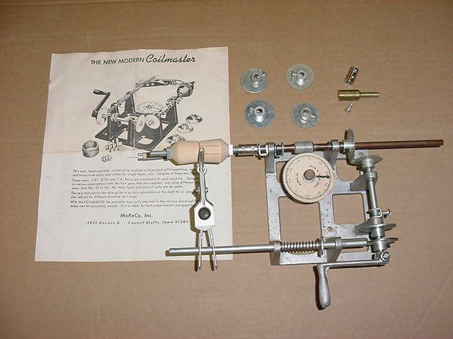
Get/Make a "Coilmaster"
This is "The New Modern Coilmaster" made by MoReCo (MOrris REgister COmpany),
Inc. of Council Bluffs, Iowa.
If you want to wind your own coils, and many people did, you
need to build one of these. They are really pretty simple as you can see
and with a little ingenuity you can make one. The turns counter is driven
off a worm gear. The spring in front is to maintain contact between the wire
guide assy and the different shaped cams, moving it back and forth. The cam
is mounted right behind the crank handle. Each Coilmaster is equipped with
four 32 pitch gears, with 39, 40, 42, and 44 teeth. This would give it a
spindle to cam ratio of approximately 0.9:1 to 1.1:1. It says enameled wire
must first be treated to give it "grip" by passing it through a quick-drying
solution, such as resin dissolved in alcohol or other similiar material.
Had you guessing too, huh ? Extra cams were $0.75 and gears were $1.00.
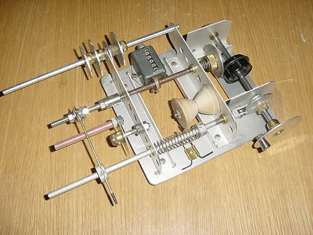
A Homebrew "Coilmaster"
This is homebrew "Coilmaster" using "whatever is available" parts. It has
a variable spindle to cam ratio from 0.9:1 to 2.1:1, various cams,
various wire feed heads, wire spool holder, turns counter, etc......even
comes with two allen wrenches. It is shown with a small plastic bobbin coil
spool mounted. Additional cams are located on the wire spool holder shaft and
also prevent the wire feed spool from coming too close. The wooden spools are
mounted on the spindle for large inner diameter coils.
The whole thing is made from aluminum scrap. Since aluminum is soft
(and easy to work), the wear points are strengthened with brass bushings from
old potentiometers. Be sure to grease all the bearing surfaces or they will
jam. All shafts are 1/4" (steel or aluminum) cut to size. The collars are made
from old knob inserts after the plastic/bakelite is removed via an application
of cold chisel. The cams are made from knobs with thick aluminum skirts
(plastic/bakelite removed). Some required a little hammer tweaking to tighten
the skirt. Since the cam is soft it rides on a small ball bearing (from an
old PC disk drive) cam follower.
The drive "gear" is a knob with a groove cut into it. A small "O" ring
is installed into the groove and contacts/drives the aluminum skirt of another
knob. A short spring is located behind the skirted knob to insure pressure
on the "O" ring. Ran into one problem on my coil winder. The "O" ring kept
"walking" off the knob on the right angle drive. After a little study, I
decided that the "O" ring footprint is not "zero", so the inside of the track
is actually running at a different ratio than the outside of the track. This
tends to cause an outward force on the "O" ring in the plane of the "O" ring
drive shaft. If the centerline of the "O" ring drive shaft is below that of
the driven plate shaft centerline, you also have the additional outward force
due to the direction of rotation of the driven plate. The way I solved the
problem is to equalize the forces by locating the "O" ring drive shaft
centerline ABOVE the center line of the driven plate (for this size plate,
"O" ring, etc it turns out that 3/32"-1/8" works best). No more problem,
everything runs true at any ratio. This was the first Engineering Change
to my coil winder .....the driving shaft bushings are now mounted in vertical
slots.
The crank is yet another aluminum skirted knob. The mechanical counter
was something from a swapmeet and lends itself to being worked with a beveled
collar. I could have used a cam to work the counter, but the counter reset
knob would have been difficult to get to. The wire feed is a small hobby shop
brass tube run through a drilled
knob insert with one set screw used to hold the tube in place and the other
used to tighten it to the shaft. This tube easily feeds #24 AWG and smaller
wire but a larger tube could be used and you can make several wire feed heads.
Most coils I need will be #28 AWG or smaller. It has a bail made from a
safety pin on the end. The wire is fed into the back of the tube and wire
tension is controlled with your fingers. A small piece of shrink tubing was
put on the end to further protect the wire. The wire feed head rests on an
adjustable bar to control height (yet another knob with aluminum skirt).
Fun project.
The additional holes in the braces are for better cooling and to decrease
weight ...Hi, Hi.
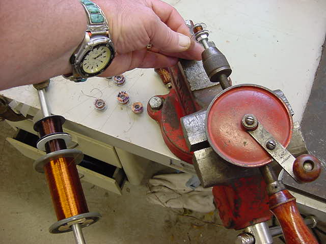
......and we have the "Cheapo-Winder"
This is "The Old Cheap Econo-Winder" used by many, including myself. It
offers the advantages of: no cams to change, no gears to change, 4x chuck to
crank ratio, infinitely adjustable, full control, able to wind multiple
strands (above photo shows three #38 AWG strands being fed onto a spool).
You are the turns counter....multiply the drill crank turns by 4.3 (this drill
gear ratio). Turn the crank with one hand, tension and feed the wire in a
pattern with the other hand. If you can "pat your head with one hand and rub
your belly with the other", you can wind coils by hand. I you can't ....see
above.
A few winding hints/ideas/observations
Your results will probably vary some from mine, but the general ideas will
hold.
- It was pointed out to me that the main advantage of a winding machine is
to allow a "basket weave" pattern which reduces adjacent turn/layer
capacitance and increases coil "Q". Basket weave also tends
to stay in place better than level wound coils because it's a diagonal
criss-cross ....and it looks cool. You can manually wind a very acceptable
"basket weave" pattern by hand with a hand drill or with a coil winder.
It doesn't have to be "exactly correct" to see the advantage of higher coil
"Q". Hand winding will generally require a spool or something to keep the
end turns from collapsing. Coil winder made coils can be wound "free standing"
if they are not too tall and you use a 2:1 spindle to cam ratio (my opinion).
- Using Litz wire or multi strand (individually insulated) wire increases
the surface area which reduces resistance at RF frequencies due to "skin
effect" (concentrates the RF current on the outer surface of the wire)
and increases coil "Q". Litz wire is useable at frequencies of 2-3Mhz or LOWER.
Above 2-3Mhz, solid wire performs as well as the Litz (from Therman's book).
The manufacturers of Litz wire twist and alternately place the conductors
relative to each other to reduce eddy currents, capacitance, keep impedance
constant, etc. The inductance of one strand is about that of two strands, is
about that of the whole bundle for Litz wire ....even though the "individual"
coil inductances are, in effect, "paralleled". This is because of the close
coupling of the wires.
- When winding with served Litz wire, you will find that it lays down easily
and makes nice coils. Solid wire (single or multistrand) will also lay down
easily if you feed it across a block of beeswax to give it "stick". You will
find that the Litz wire does have higher "Q" but it's "bulkier" than the
equivalent solid wire (will take up more space). Litz wire will have a
tendency to kink as it comes off the spool due to the wire twist.
- To measure the capacitance between conductors of bifilar or Litz wire,
measure only a foot or so of wire and extrapolate to the total length (via
resistance measurements). If you measure the capacitance on the spool, you
will see a very small (in error) reading. The reason is that you are trying
to measure capacitance across two really good RF chokes with a tester which
uses an RF frequency to determine capacitance.
- Litz wire is sometimes a little confusing. For example: 6/44 unserved
Litz wire means 6 strands of #44 AWG wire without an overall wrap (unserved).
The AWG "equivalent circular mills" for 6/44 Litz is #36 AWG. This means that
6/44 Litz has the same circular mills and DC current handling capability
as one #36 AWG wire. However, the RF current resistance of
6/44 Litz is less than half that of the #36 AWG wire and approaches that of
#28 AWG wire. What all this means for the coil is that 6/44 Litz will have a
higher "Q" than the equivalent solid wire of equal DC current capability
(#36 AWG), but it will take up more space. Unserved 6/44 takes up the space
of #34 AWG and served 6/44 takes up the space of #32 AWG.
- From what I've seen, manufacturers of small IF transformers in the 100Khz
to 455Khz range use single #38 AWG wire (good), bifilar #40-42 AWG wire
(better) or trifilar #44 AWG wire (best) for the windings (allows 18-28ma DC).
The smaller JW Miller 100Khz IFs also have a ruberized "powdered iron?" layer
inside the aluminum can. I believe the reasons for this layer is to further
increase permeability and to isolate the coil from the can. The fact that
100Khz IFs require 5-6mH of inductance dictates a physically large coil, the
large coil results in increased capacitive coupling to the can, which reduces
"Q" and overall inductance. The higher permeability and resultant higher "AL"
value (uH/100turns) is needed to keep the overall coil size manageable in the
smaller 3/4" square IF shields.
- Spindle to cam shaft ratios for small IF type coils seem the be 2:1. This
means the wire feed head traverses from one side to the other in one spindle
revolution and traverses back during the second spindle revolution. I don't
think a Morris "Coilmaster" can do that. A 1:1 spindle to cam shaft ratio
means the wire feed head traverses to one side and back during one spindle
revolution.
- Tuning slug/cup material permeability can vary substantially (just like
toroids) and Amidon lists permeabilities up to 35 for their slug tuned coil
forms. The 0.01 to 0.50Mhz "3" material has a permeability of 35. As an
example: one 455Khz IF (which you would expect to have a high permeability
slug) measures 0.7mH without a slug, 1.5mH (max) with it's powdered iron slug
and 2.5mH (max) with another powdered iron slug from a JW Miller 100Khz IF
(obviously with a higher permeability). Some of the physically small coils,
like those in 3/8" cans use very high permeability ferrite cups to reduce
coil size requirements.
- When swapping tuning slugs for one you just had to drill out because it
broke, make sure the permeabilities are about the same or it won't tune
correctly. Could never get that Heathkit HF osc to peak....huh ?.
- One source of low frequency, high permeability slugs is old TV horizontal
osc coils. If you need to shorten a powdered iron slug, scribe it with a
hacksaw and snap it by hand. A simple method for determining relative
permeability is to swap slugs in a given coil form and measure the inductance.
- Coil spools solve the problem of the end turns "collapsing" on small
coils, especially if you are not using a coil winder. The coil spools used
are plastic "Singer" Class 15 (11/32" tall winding) or "PFAFF" (7/32" tall
winding) sewing machine bobbins available at any sewing store (or the wife's
sewing room ....but be careful, they don't share your enthusiasm).
Coil winding using the wife's sewing machine "bobbin winder" does not work
and can shorten your life. A "Singer" Class 15 or "PFAFF" bobbin has a
thicker core and lends itself to being drilled out to 19/64", 9/32", or
17/64" which allows them to be put onto standard 1/4" slug tuned cores.
Trim the spool with wire nippers and since it's an outside curved edge, a
finger nail clipper works well. Trim the spools after you have wound them to
keep the newly created
rough edge from cutting small gauge wire or smooth the spool edge before
winding. If the spools are not the correct height, cut them in half or make
some "washers". It's important to secure these solidly to the coil form
or the winding will tend to "walk" the washer ends outward. When done,
carefully remove the washers and add some beeswax/Q dope to seal the outer
turns.
- To keep the initial turns from slipping add a layer of double sided tape
to the core or drip some beeswax onto the core (preferred).
- Many types of magnet wire allow direct tinning of the wire which burns
off the insulation in the process. This is MUCH easier than scraping the
insulation off with a razor blade, especially for the smaller gauges. Burning
off the insulation over a flame is not advised.
- Aspect ratio is important. A fixed length of wire was wound on a given
form and slug. The coil winding height on one was 3/8" and 3/16"
on the other. The 3/16" winding (larger outer diameter) measured 40% (max)
more inductance. Therman says optimum inductance is achieved if the winding
cross section is square. Slug tuned coils may be different.
- To give the wire more "stick" as you are winding, feed it across and into
a beeswax block (available at art/craft and sewing stores).
Factors Affecting Coil Q ...some experiments
EXPERIMENT #1 ....Skin Effect
Four coils were wound by hand. Coil Q will increase if the turn-to-turn
capacitance is reduced. This can be accomplished by using a "basket weave"
pattern. The "basket weave" coils have roughly 1-2 spool length traverses
of the wire per revolution of the spool (coil Q will be even higher on fixed
pattern wound coils made using a coil winder). Q can also be increased by
using multi strands of smaller gauge wire due to increased surface area (skin
effect) at frequencies below about 3Mhz. It's a substantial improvement in Q
to use two strands of #39 AWG vs one strand of #36 AWG, or better yet
.....six strands of #42 AWG vs one strand of #36 AWG. All three of those
examples have the same current handling capability. Many small, higher
quality, IF transformers are wound with two strands of smaller gauge wire.
Larger, high quality IF transformers are wound with Litz wire, dipped, etc.
All coils were trimmed to 2.0 mH with no slug, and 3.0 mH with a slug.
Q Data is "unloaded Q" as measured on a Boonton 260-A.
At 200Khz, all coils trimmed to 2mH, no tuning slug
- Coil #1 #34 AWG, level wound, 325pf, Q of 52
- Coil #2 #34 AWG, basket weave wound, 320pf, Q of 55
- Coil #3 two #38 AWG, basket weave, 310pf, Q of 78
- Coil #4 three #38 AWG, basket weave, 320pf, Q of 83
At 170Khz, all coils trimmed to 2mH, no tuning slug
- Coil #1 #34 AWG, level wound, 440pf, Q of 55
- Coil #2 #34 AWG, basket weave wound, 447pf, Q of 57
- Coil #3 two #38 AWG, basket weave, 433pf, Q of 78
- Coil #4 three #38 AWG, basket weave, 446pf, Q of 85
At 150Khz, all coils adjusted to 3mH with the tuning slug
- Coil #1 #34 AWG, level wound, 400pf, Q of 82
- Coil #2 #34 AWG, basket weave wound, 380pf, Q of 85
- Coil #3 two #38 AWG, basket weave, 380pf, Q of 109
- Coil #4 three #38 AWG, basket weave, 385pf, Q of 114
EXPERIMENT #2 ....Coil Form Dielectrics
Other factors which effect coil Q are the coil form material and the
adhesive used to hold the windings. Any coil form which can absorb moisture,
like the old cardboard oatmeal boxes and toilet paper tubes used for crystal
sets, is a problem unless the cardboard is treated with varnish, shellac, etc
....but it's cheap.
Some have suggested using old plastic pill bottles which is OK if they
are sturdy so the coil turns don't move. Recently some testing has
shown that coils wound on those amber pill bottles have just has high a "Q"
as those wound on the Amphenol 5-pin forms. Some PVC is the same way. What
does affect "Q" is the material you use to coat the windings (materials
to be tested later ...beeswax, refined paraffin, varnish, laquer, other
"glues"). Here is an example of coils wound (adjacent turns) with #28
AWG magnet wire:
| "Q" at 6 Mhz with all coils measuring 20.5uH |
|---|
| Reference | Note 1 | Note 2 | Note 3 | note 4 |
|---|
| | | | | |
|---|
| 1-1/4" Amphenol 5-pin | 175 | -- | 175 | -- |
| 1-1/4" amber pill bottle | 180 | -- | 177 | 172 |
| 1-1/2" amber pill bottle | 161 | 147 | -- | -- |
| 1-1/4" untreated cardboard | 152 | 130 | -- | -- |
| 1-1/4" PVC | 173 | -- | 175 | -- |
Notes:
- Plain wiring, no adhesives, no tape to hold windings
- Use a light coat of clear fingernail polish to hold windings (strips
across windings didn't work), Q reading 15-20 points lower when first
applied, above readings are after 48 hours.
- Use Elmer's Stix-All silicone to hold windings (4 strips across coil
windings)
- Use Scotch black electrical tape to hold coil windings (1-1/2 turn)
EXPERIMENT #3 ...Turn Spacing
The highest Q coil for a given inductance is "air wound" with space between
the turns (less turn-to-turn capacitance), the next is space winding on a good
coil form (ceramic, phenolic, etc). Space winding on a coil form by winding
string or another wire along with the coil wire and removing the "spacer"
later is good. Ceramic and some phenolic coil forms came with wire groves to
space the turns. You do have the problem of having to stabilize the separated
turns with Q-Dope, paraffin, Duco cement, etc.
Here is some data on two coils:
- 1-1/4" coil form (amber pill bottle)
- both coils 13.8uH +/- 0.1uH
- both coils #28 AWG wire
- coil "A" 16 turns are adjacent
- coil "B" 20 turns are on .025" centers +/- (spacer was removed)
- both coils, no adhesives/coatings to hold the turns in place
At 3.4MHz ..... coil "A" Q=107, coil "B" Q=175
Granted, these are unloaded Q measurements on a Boonton 260-A and
loaded Q will be less, however the improvement will be carried over
and the "trend" is there.
What does this mean for the signal (loaded Q will be less dramatic):
- Sensitivity ...the Boonton uses a 20mVAC "e" signal and measures "E"
with a very sensitive voltmeter, so a Q of "107" means "E" is 2.14VAC
....a Q of "175" Q means "E" is 3.5VAC ....higher sensitivity.
- Selectivity ....Q is also the -3db voltage BW divided into the frequency
(Q = Fo/-3dbBW ...or -3dbBW = Fo/Q). For a Q of "107" the -3dbBW
is 31.8Khz. For a Q of "175" the -3dbBW is 19.4Khz .....better
selectivity.
EXPERIMENT #4 ....Coil Dope
"E6000" Craft Glue was used on a coil with a Q of "175" ...absolutely no
change in Q as you put the material on, as it dries, or 24 hrs later, even
for a very heavy application of glue. I believe it's some kind of silicone
based product .....waterproof, clear, and remains flexible. My wife didn't
even tell me she had some "really good coil dope" material in her crafts pile.
"CG Clear Ice" fingernail polish was used on a coil with a Q of "107"
and the Q dropped to "97".