
What to do! The first thought is "get rid of the offending signals". We wanted to pass only a 6 MHz. wide band of signals from 438.00 MHz to 444.00 MHz. and get rid of everything else! We built a 7-pole interdigital filter based on dimensions from a computer program written in Basic that appeared in an old issue of Amateur Television Quarterly magazine. It apparently worked, as you can see from the filter responses. Before we installed the filter, we could see all sorts of garbage including a hetrodyne image of nearby channel 18 on our repeater receiver monitor. After installing the filter, there is only snow on the screen. There is no hint of any other interferring signals.
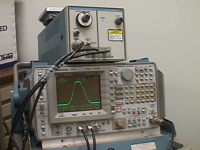
With seven adjustments, the tuning of the filter can be a real can of worms. The best way to do it is to use a very expensive network analyzer (presumably because you can also measure phase shift through the filter - it distorts the color of your signal). The second best way (almost as expensive) is with a sweep oscilloscope and tracking generator. Worst is by guess and by golly! We used the second method because that's what our resident Professional Engineer had available! Here's the setup, and the scope display of the tuned filter:

(last updated 1/1/2001)