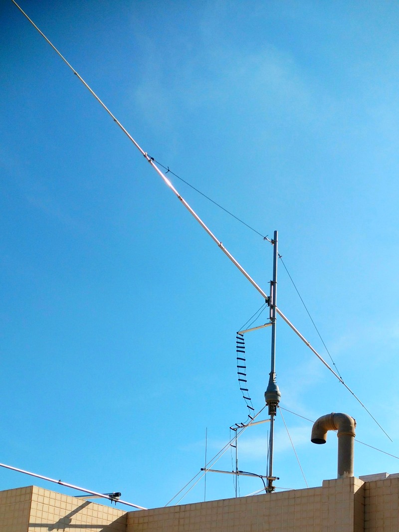

Several people have asked about my antenna, so I thought a discussion of what I am using and how I got there would be of general interest.
I am lucky enough to have an apartment on the top floor of a 10-story apartment building. Part of it is a small room located on the roof that is accessible from the rest of my apartment by a stairway, and that is my shack. The roof area of this room is a rectangle of about 3m x 6m, and that is where I can put my antenna.
I’m allowed to install a vertical or a dipole. I’m primarily a DXer, so I need as many bands as possible. I decided that I could live with 40m and up.
My first antenna was a Cushcraft R-8 vertical. Although it performed adequately, it was never possible to adjust the 20 and 17 meter bands to my satisfaction, so I had to use a tuner on one or the other. It developed an arc in the matching box which I fixed, and then a bad connection in one of the traps (which MFJ replaced under warranty). Mechanically I felt it was marginal, even though I had it guyed at two levels. And lowering it to adjust it was very difficult and required help.
I thought a horizontal antenna would give me a bit of gain over the vertical and be quieter. At about 35m above ground, it should work well. I bought a ‘Despole’ antenna from InnovAntennas. The one I chose had three parasitically coupled dipole elements, for 20, 17 and 15 meters. The elements have dropped ends, so they fit nicely in my limited space. I had to make a few minor modifications to keep the strong winds here from bending the dropped ends upward, but once I got it adjusted it worked very well on its designed bands, and I was able to use it on 12 and 10 meters with a tuner. It even worked to some extent on 30, although performance was way down. 40m operation was impossible.
The available space permitted a full-size 20m rotary dipole. EZNEC indicated that it would perform more than adequately on all bands from 40 through 10 – if I could match it without excessive losses. I built such a dipole; but how to feed it?
One solution would be to install a remote tuner and balun near the feedpoint. But the only affordable candidate is the MFJ-998RT, and I was a little leary of trying to use it with the 1.2 kW output from my amplifier. I wasn’t sure it could handle the extremes of impedance it would encounter. It would be prone to damage from static electricity and lightning, and when you consider the shipping costs and Israeli taxes, it wouldn’t be all that ‘affordable’. And reviews indicated that reliability was questionable.
I decided to use open-wire line and worry about the matching in the shack. I needed only about 10m of line, and I hoped the losses would be acceptable. I bought some “True Ladder Line” which uses flexible no. 16 wire and insulators made from polyethylene irrigation tubing. EZNEC gave me an impedance of about 13.5 –j689 ohms at the feedpoint, which produces an SWR of more than 80:1 on 600-ohm line! But because the line has little loss to begin with, the total loss with SWR is less than 3 dB. That’s a lot of power, but 600 watts to the antenna on 40 meters is better than no watts on 40. And it has proven to be very effective in the pileups. On other bands the loss is almost negligible.
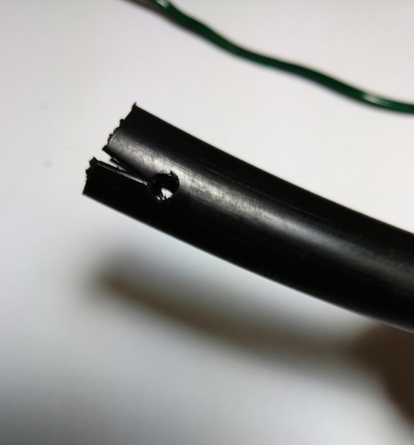
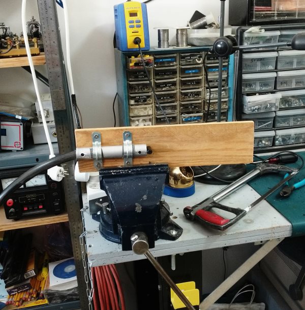
A few months ago, I decided to reduce the loss even further. I replaced the True Ladder Line with homemade open-wire line made from no. 12 insulated “Flexweave” wire (Wireman no. 545). I made a simple jig from a piece of tubing that would allow me to cut 1/2" PE irrigation tubing to the correct length and drill holes for the wire at the ends. After drilling, I cut a little slice at each end near each hole to allow the wire to snap into place. My new spacers provide a wire spacing of 4”, which results in a characteristic impedance of 470 ohms when used with no. 12 wire. Although the SWR on 40 meters is close to 100:1, total line loss is now only a little more than 1.3 dB!
When I first built the antenna I used the center section from the DESpole. It was fine for a low impedance feed, but couldn’t take the high voltages developed when the load was highly reactive. Plastic insulators melted and burned, and slightly magnetic stainless screws got extremely hot. I rebuilt the center section with a fiberglass tube and plenty of clearance.
At this point I found that while my tuner could match the antenna, its built-in balun immediately overheated. I got a 5-kW balun from DX Engineering, but even that heated up on 30 and 40m. Time to stop throwing money at it and get smart! I had done some experiments in the past that showed that balun efficiency was very poor when working into a reactive load. So I had to get rid of that reactance. Although the antenna shows a large capacitive reactance at the feedpoint on 40 and 30m, the line transforms it. In the case of 40m, the impedance at the shack end has a high inductive component, while on 30 it ‘wraps around’ and becomes capacitive again.
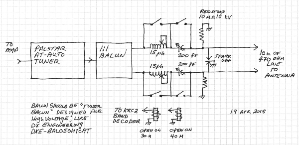
I had a couple of HV SPDT relays in my junk box, a couple of 250 pf 4500V variable capacitors and some coil stock. I also had a KRC2 band decoder which works with my K3. I put both the coils and capacitors in series with the line, and set up the KRC2 and relays to short the capacitors on all bands but 40m. The coils are shorted except on 30. I adjusted the capacitors and the coils to tune out the reactance on those bands, leaving a resistive impedance that will put less stress on the balun.
I initially used a 4:1 balun because it seemed to work better on 40m. But there were problems with RF in the shack, and matching was difficult on some bands. I rewired the DX Engineering balun to convert it to 1:1, and those issues went away.
It works! The SWRs at the unbalanced side of the balun are less than 7:1 on all bands (on 40 and 30, previously the worst bands, it is around 3:1). The tuner has no trouble matching it and the balun stays cool.
For a future project I am thinking about a dedicated matchbox to mount at the feedpoint. It would contain relay-switched components to get the antenna into the ballpark on all bands – SWR of say 3:1 or less – and a 1:1 balun. Then it could be fed with coax, with final tuning done in my shack. The line would be short enough that even with coax, losses would be low.
Here is a schematic of the "pre-tuner" which operates on 40 and 30 meters:

Here is a picture of the end of a spacer made from 1/2" PE irrigation tubing:

And here is the jig for making spacers. Push the tubing in, drill it, cut it off, and you're done.
