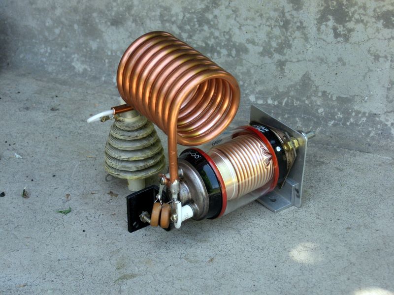
| This is the clever
coaxial tank circuit. The coil is used for 20-10 meters, and the DC
connection for the HV passes through it, exiting at the low impedance
point. The large RF choke shown has an inductance of several mH, so it
provides a high reactance on 160 meters without worries about
resonances on the bands above 40 meters. Ultimately I replaced this with a conventional parallel feed, but I thought it was cool, so here it is. |
 |
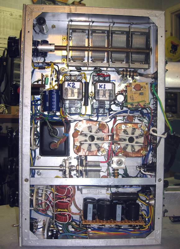
| Here is the
under-chassis view.
The HV power supply and input circuit are at the bottom. The
compression trimmer just above the partition is half of the bridge
neutralization circuit; there is a fixed plate above the chassis near
the tube plates. Neutralization is done by adjusting this trimmer. Note the copper sheet on the tube sockets. The idea is to provide a good common ground for the various bypasss capacitors. A little 'tongue' of copper passes through the socket hole and is bolted to the top of the chassis, to provide the shortest possible return path from the plate circuit to the filament and screem bypass capacitors. Does it help stabilize the amplifier? Who knows? The transformer to the left of the sockets is for the screen and bias supplies; just above it are the power and soft-start relays. T/R switching circuitry is to the right of the relays. |
 |
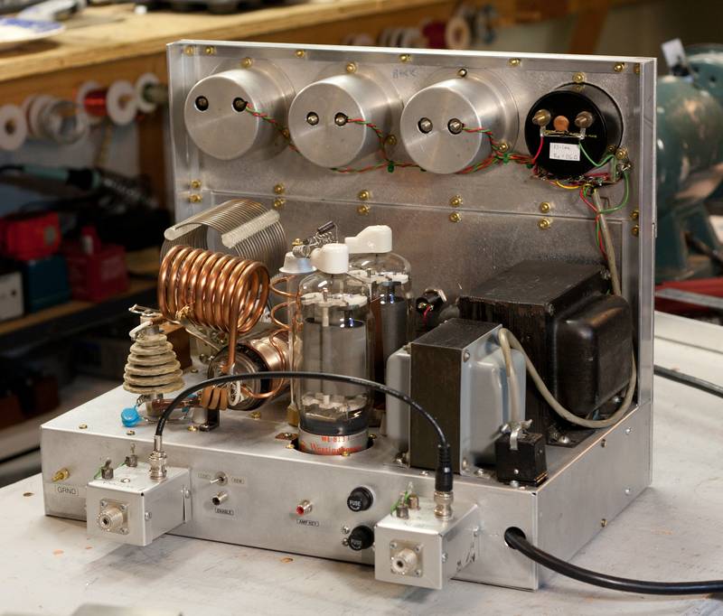
| The amplifier seen from
the back.
The little boxes at the back contain the T/R relays (see next picture).
My theory was that it is good to isolate them in a high-gain amplifier,
such as this. Note the feedthrough capacitors on the boxes. Latter I
added a box containing a line filter where the power cord is. You can see the completed tank circuit. The big coil is for 160-40 meters, and the tubing coil is for 20-10. This was entirely redone when I changed to a conventional paallel feed. The vertical spiral between the tubes and the tank circuit is to provide a small amount of inductance between the tubes and the pi-network, making it an "L-pi." This made it possible to obtain a reasonable Q on 10 and 15 meters, for good efficiency. This picture was taken before the enclosure was built. The enclosure has a muffin fan located above the tubes. |
 |
| Here are the contents of the little boxes. | 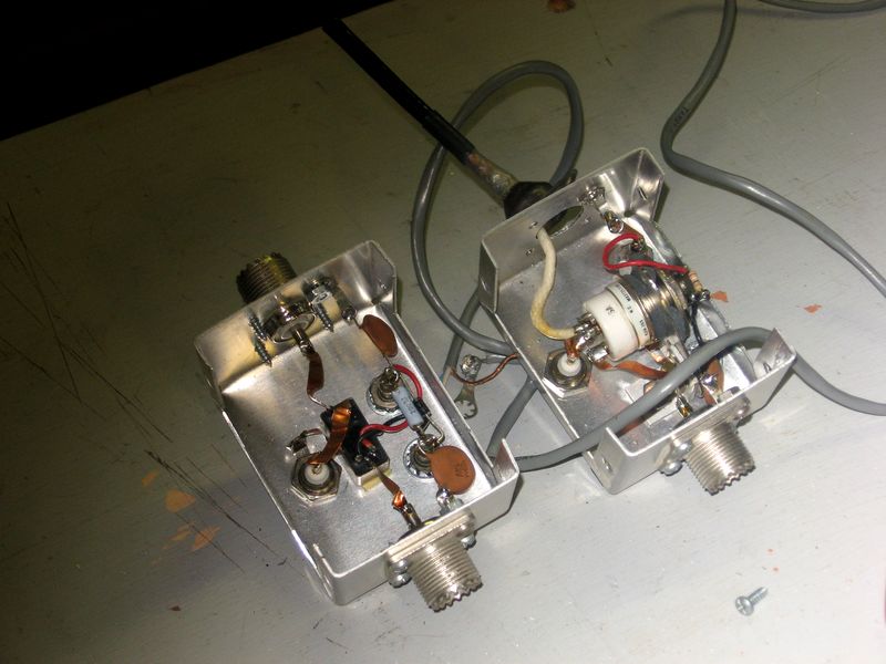 |
| The link-coupled input coils and the grid bandswitch. I later replaced the 10-meter coil with an air-wound version, for slightly more efficiency. | 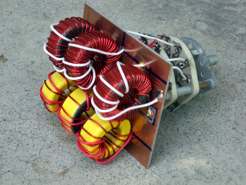 |
| The HV power supply board. Only a total of about 19 uF, but I don't hear any hum. And even if I did, this is a 1955 design! These capacitors are somewhat old, but I used my ancient Eico resistance/capacitance tester to make sure they were formed up and held full voltage | 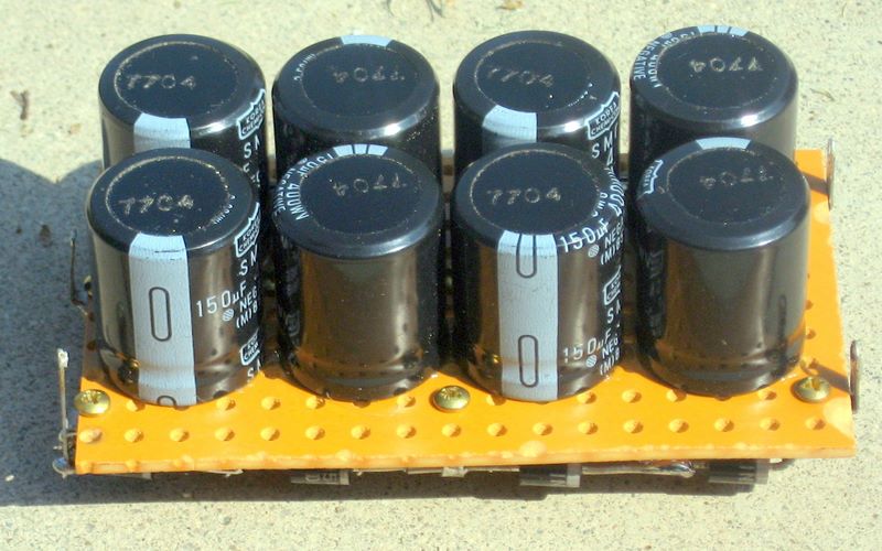 |
| A bad 813 I bought on EBay. Note the broken filament coil. The guy said that the tube 'looked unused' and the damage must have happened during shipping. The carbon plate was very badly pitted, too. I got my money back, but was out the shipping cost. Caveat emptor on EBay! | 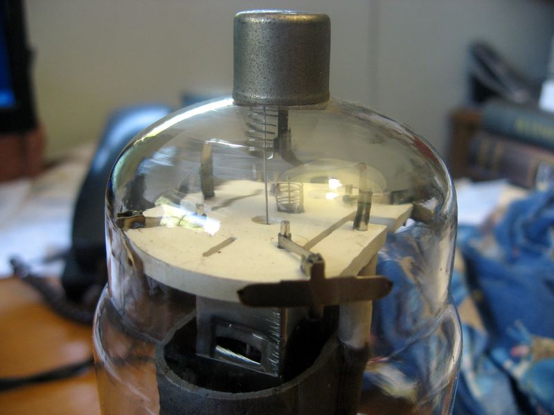 |
| I had intended to document the construction as I went along, but I didn't do a good job of it. Here are some of the parts I started with -- you can see that I made some changes, like the vacuum capacitor instead of the bread slicer shown. | 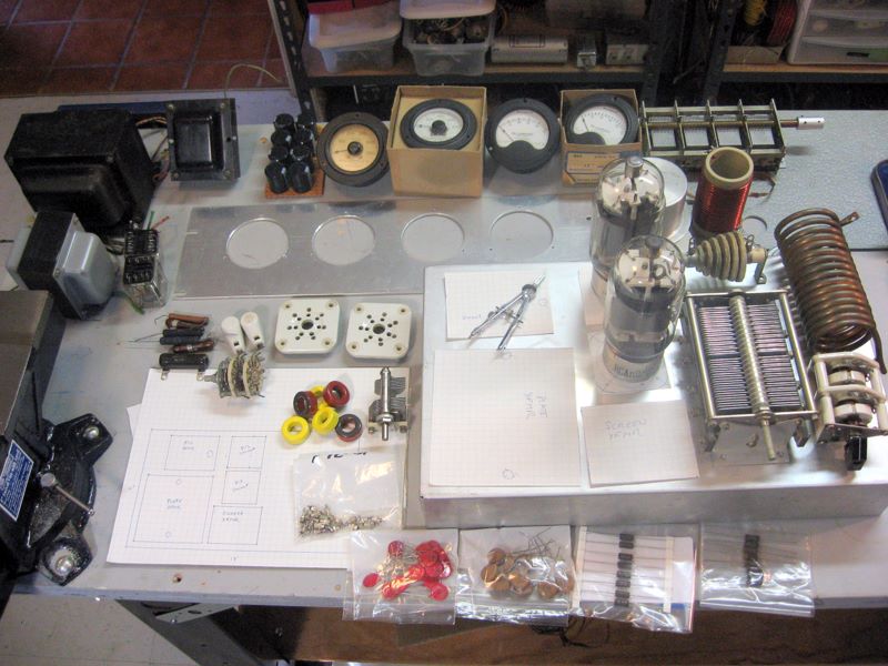 |
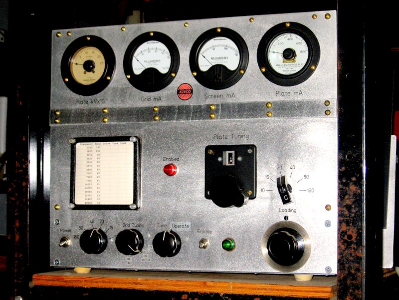
| Here I am before building the enclosure or mounting Kurt's chart frame. Boy, I am happy it's finished. | 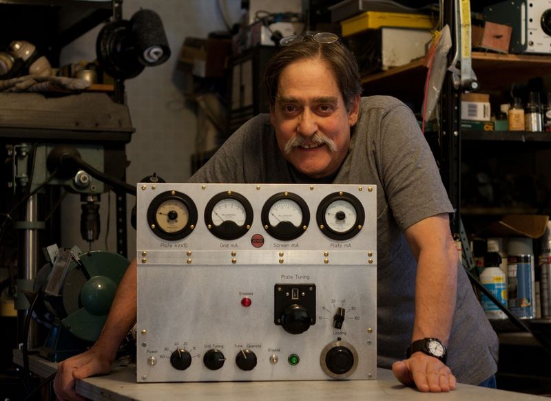 |