A Really Simple LF Receiving Loop
While trying to fight a problem with noise from a remote-reading power meter that the electric company had just installed, I decided to try an isolated single-turn loop, as far from the house as my roll of coax would reach. The present remote-tuned, balanced loop is about 70 feet from the house and was picking up a lot of impulse noise from the meter. I assumed that the noise was primarily conducted via the power, tuning and rotator cables leading from the shack to the loop.
Mitch Powell has been having such good success with a receiving loop suspended in a tree that I decided to do the same thing. My original plan was to make an X-frame of PVC pipe with 15 foot diagonals. The local hardware store had some pipe that looked much bigger than necessary, and some flimsy-looking ½ inch stuff. Not much in between. Since there wasn’t going to be much load other than the loop wire, I figured the ½ inch PVC would be adequate. Unfortunately the stuff was like a wet noodle, and didn’t survive being dragged across the rail fence leading into the pasture. Then it occurred to me that there was no need for an X-frame on a wire loop suspended in a diamond configuration. All it needs is a horizontal spreader in the middle. Actually, you could get by without even the spreader and pull the corners out with ropes, but the spreader seemed easier. The figure below shows schematically what the whole thing looks like. A rope thrown over a tree branch is tied to the top of the loop and serves as the support line. The same rope, or another lighter line, continues down and is tied to the middle of the spreader to keep it from sagging. At the bottom, another rope looped over the matching unit enclosure keeps the loop in position and provides tension in the wire so that it maintains a square shape. A bungee cord or spring at this point might be a good idea; however I found that the bending of the spreader served the same purpose and seems to maintain about the right amount of tension.
In parts of the country where the ground isn’t frozen, the tie-down rope can be attached to an anchor driven into the ground. For me it was more convenient to tie it to a large chunk of wood. A rock, as shown in the diagram, would work just as well, but it’s hard to find rocks in my pasture without using the mower. To hold the loop at a particular angle of rotation, another rope is tied to one of the side vertices. I used 3/16 inch UV-resistant "antenna rope" for the top support and tie-downs, and 1/8 inch Nylon cord for the rotator line. As with the tie-down, the rotator line can be tied to a convenient branch, ground stake, or heavy object.
PVC pipe, perhaps about 1" diameter, would make a good spreader material. Lacking that, I scrounged through my tubing pile and found a 12 foot length of 5/8 inch aluminum tubing. With the two halves of a 4 foot fiberglass electric fence post stuck into each end, it easily made the desired 15 feet. The 3/8 inch fiberglass posts were a sloppy fit in the tubing, but that was easily fixed with a few wraps of duct tape, and the rods were secured with screws.
Probably #14 wire would work just fine, but bigger is better, and I had a good stock of #10 insulated building wire. With a 15 foot diagonal, the sides of the square loop are approximately 10 feet 7 inches. I took about 42.5 feet of the wire and formed a small "eye loop" in the middle to attach the suspension rope. To make the eye loop, you can make a single wrap around a screwdriver handle and twist it. However, I used a plastic electric fence "corner insulator", which lended a touch of elegance to the project. I drilled a hole near each end of the spreader (3/16" is a good fit for #10 insulated solid wire) and threaded one side of the wire through each hole. I slid the spreader along the wires until it was 10.5 feet from the support eye on both sides; then made a half-turn loop of wire around the spreader to hold it in position. A photograph of the end of the spreader with the rotator line attached is shown below.
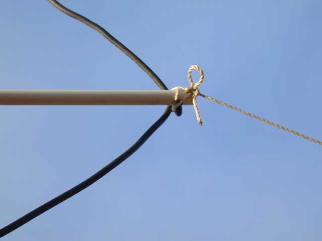
Loop wire and rotator line attachment to spreader end
The free ends of the wire were inserted into 3/16 inch holes drilled into the matching unit box, which is a Radio Shack 270-1801 Project Enclosure. This box is only 3 X 2 X 1 inch, and although it is adequate for this job, a bigger enclosure wouldn’t hurt. The picture below shows how the wires are routed into the enclosure to provide strain relief. The wires enter near the top of the box and are bent around the support posts, then held in place near the bottom of the box by screws and washers. There are four short posts in the box that can be used for mounting a PC board. No screws are provided with the box, but I had some short self-tapping screws (probably #6) that worked fine. With the screws holding the wires in place and with the stripped ends bent upwards, the loop wires themselves serve as terminal posts for attaching the leads from the transformer and series tuning capacitor. Tuning may not even be necessary, but it seemed like a good idea to tune the loop for the most active portion of the LowFER band, around 185 kHz. Reg Edwards’ RJELOOP1 software predicted that the required capacitance would be about 0.039 uF. I didn’t have that value in my junkbox but used a 0.033 uF and 0.006 uF in parallel.
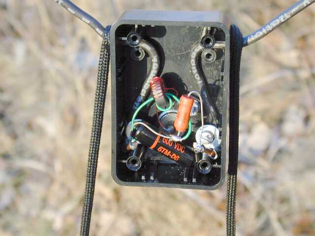
Matching unit
Theoretically the series resistance of this loop at resonance would be well under 0.5 ohm. However, I figured that with ground proximity and capacitor losses, a 100:1 impedance ratio (10:1 turns ratio) in the matching transformer would be about right. The transformer in the picture is an FT-50-77 core with two turns on the primary and 20 turns on the secondary. The core is hanging by the leads of the 20-turn secondary, which are connected to the SO-239 coax connector mounted on the back of the enclosure. The 0.039 uF capacitor connects between one end of the loop and the 2-turn primary of the matching transformer; the other side of the primary winding goes to the other end of the loop. My homebrew analyzer showed an impedance dip down to about 60 ohms in the vicinity of 187 kHz, so the turns ratio on the transformer is certainly close enough for receiving purposes.
It's hard to fine tune a 0.039 uF capacitor, especially when you're sitting out there with a portable soldering iron and the loop swinging in the breeze, trying different capacitor combinations. Someday, when it warms up again I'll try resonating the coax side rather than the loop side. That should require only 390 pF and would allow the use of a variable capacitor. My gut feel says that there will be more core losses that way, but it might not be important in a receiving application. Another experiment will be to short out the capacitor and see if it is really necessary.
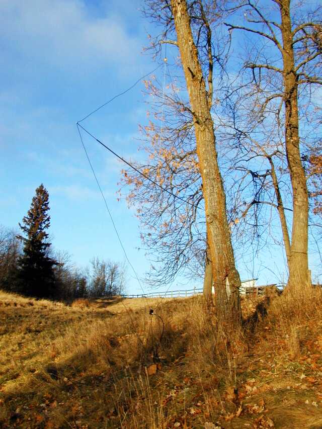
The finished antenna is shown below. A portion of the loop, including the end of the spreader with the rotator line attached, is hidden from view by the tree that supports it.
OK, what about results? As for rejecting the noise from my remote reading electric meter, I couldn’t tell any difference by ear between the single-turn loop and my balanced loop. LowFERs RM and BRO from Duluth, MN, about 70 miles away, were buried in the noise on both loops unless the receiver’s noise blanker was turned on. With the noise blanker, both signals were easily audible on both loops. Not a very definitive test, but obviously there was not the dramatic difference that I had expected. In addition to the isolation provided by the transformer in the loop matching unit, I had inserted another homebrew 1:1 isolation transformer. At first the second transformer was between the battery-operated preamp and the receiver in the shack. Later I moved it out to the woodshed where there was a splice between an existing run of coax and the new coax going out to the loop. The second transformer made no difference no matter where it was placed. I concluded that either the noise from the meter was not entirely confined to the power wiring, or my transmitting vertical was somehow re-radiating the noise. (Both loops are about the same distance from the transmitting antenna.) I planned to scout the area with a portable receiver to try to find a quieter location, but the day after I put up the loop, the power company installed a filter that seems to have killed the meter noise. There went my noise reference, but I didn’t feel bad about it at all!
Later I made a more quantitative comparison of the signal from LowFER BRO (182.2 kHz) on both loops. The balanced loop has its own preamp, located at the loop, and I used my homebrew "universal preamp" in the Low-Z position to amplify the signals from the single-turn loop. Signal levels were at least 10 dB weaker on the single-turn loop, which I didn’t worry about – that’s simply a matter of preamp gain. It’s the signal to noise ratio (SNR) that counts. Using the spectrum analysis feature of CoolEdit, I could see almost no difference in SNR between the two loops. That result is expected, if both loops are sensitive enough to get to the receiver/preamp noise floor. Besides BRO’s signal, there were multiple lines in the spectrograms, and they all had essentially the same amplitude on both loops. That was a little bit surprising – I figured that quite a few of the signals that I see all over the LowFER band are originating from computers and other equipment in the house. Maybe that stuff is not of local origin after all! Either that, or the isolation transformers and increased separation to the new loop were doing absolutely nothing.
The next test was to turn on a known source of interference in the house to see if the new loop made any difference. There is a great source of LowFER band noise (and usually a very precise frequency reference) in every TV set. The 12th harmonic of the horizontal oscillator falls at 188,811.1649 kHz, and it has nice buzzy sidebands for some distance above and below that frequency. On my balanced loop, the TV horizontal oscillator does a real number on LowFER RM at 189.8 kHz, although I can still copy him by using a very narrow filter. Switching to the new loop, the TV interference disappeared. Just about then I started noticing audio in the background. Iceland Radio on 189 kHz was beginning to come in. With the TV set off, the audio was fairly good copy in LSB mode on both loops. Slightly more noise on the balanced loop; probably from one of the computers in the house. Turning on the TV set totally obliterated Iceland on the balanced loop; on the new loop it was hard to detect whether the TV was off or on. Hey, it works!
During these tests, both loops were oriented NE-SW, which places the house near the null of the new loop’s pattern, and at the peak of the pattern for the balanced loop. This accounts for some of the difference in noise pickup, but I expect that the isolation transformers and increased distance from the house are doing their bit as well.
In a side-by-side test, receiving LowFER "FAW" from Riverton, UT (1000 miles), the single-turn loop and an IC-756PRO receiver gave slightly better copy than my balanced loop/preamp and an IC-706. (My "universal preamp" was used in the shack in front of the IC-706.) Whether the difference in copy was due to the receiver, antenna, or simply the Argo settings on the two computers is not known for certain. But the bottom line is that the simple loop can do a very respectable job of receiving distant LowFERs.