Rotators
and thrust bearings
Antenna
use has grown with our station capabilities here. We currently use seven
different antennae here. On this small city lot, it has presented some
challenges. Here are some of them-
- The lot is only
40’x120’
- The area is
completely developed. Even the trees are fully grown.
- The house has a
roof pitched 12/12
- Our backyard is
only 40’ square between the house and garage. It has a full grown tree in
the middle.
- Power lines run
into and border on the rear of the property. There is also phone and cable
overhead.
- There are three
trees taller than my house, all within 20’ of it.
I
have a couple of self imposed limits too:
- No use of tripods
or any structure that makes holes in the roof.
- No towers, since
almost any configuration here is within falling distance of a power line.
Given
these limitations, it was decided to locate an antenna rotator on the top of
the house, as close to the center as possible. It took four iterations to get
to where we are today.
My
sweet wife is very understanding of my hobby. She has few requests and they
have all been extremely reasonable. Since I have no wish to test the limits of
this understanding, and I also have no wish to discuss ham radio with city code
officials, I wanted to build a rotator that suited my needs and was as discrete
as possible.
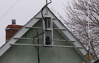
I
put up my first Cushcraft 2 meter 4 element boomer on a TV antenna rotator
strapped to the chimney in 2006. I later added a loop for 6 meters to the gable
end on the left. It’s tough to see in the photo below.
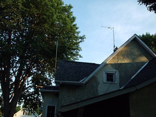
Let's call this Rotator
1.0, 2 meter boomer on chimney w/ TV antenna rotator. Probably taken in 2006,
maybe early 2007. On the left is a 6 meter loop.
Our
chimney is very loose to begin with. It’s not fall-off-the-roof loose, but a
spalled bit of brick landed on a neighbor once. I’ve since put a new top
on the chimney and it has two bands around it to hold it together. The chimney
is not a good candidate to hold up an EME array, however. I think that has to
be true in any house near this age.
There
were problems from the start. The antenna flopped up and down several degrees
vertically in one rotation. Partially due to the rear antenna mount, but
partially because the rotator and mast are inadequate even for such a small
antenna. The bracket and straps simply could not hold the antenna still. Using
this antenna quickly demonstrated to me that I wanted a larger one and I knew
that the rotator would have to be improved to handle it. I also hoped to be
able to have more than one band on the rotator. At this point in my evolution,
I didn’t even consider a 6 meter antenna on the mast. I thought it would be too
large. I had been looking at how this problem is solved for folks who have
towers, and learned that the rotator sits inside the tower and side thrusting
on the rotator is braced by having a thrust bearing at the top. These forces
would otherwise quickly damage a rotator holding up a large mast.
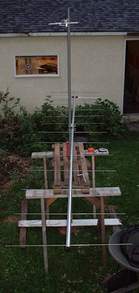
Below
is a photo of the next setup being built and then up on the house. The frame
and bearing of the rotator are made of treated wood. I used another piece on
the side to hold the bearing in place. The bearing is screwed and glued to the
back board that also mounts the TV rotator. I used a hole saw and made a nice
oversize hole for the mast to go through. The back board was fastened to the
house with 2 pieces of square tube screwed to the fascia board. In this house,
that’s 1’ pine boards that are about 100 years old. I screwed the brackets in
twice on each end. Galvanized was used for most hardware.
The
antennae at this point were a 10 element 432 cushcraft and a Hy-Gain VB-214FM.
This was a low budget operation.
The
mast being built is on the left. A photo of the installation is in the middle,
and on the right is a photo of the rotator after it was removed.

Rotator 2.0
While
this was fun to make, it never worked as well as one might have wished. The TV
antenna rotator only ever rotated about 330 degrees, and was always off by
about 15 degrees. I even bought a new rotator for this attempt. Nevertheless,
it was in use for a year.
I
wanted to continue to use a TV antenna rotator because they are cheap and
readily available. After all, a small bunch of antennae are not much bigger
than a big honkin’ TV antenna anyway. Besides the rotator, I thought the wooden
bearing surface must be the next thing that could be improved upon. I decided
two bearings would be better, that way the motor could almost float and highly
accurate alignment of the rotator and bearings would be less important.
Here
is the third version after it was removed:
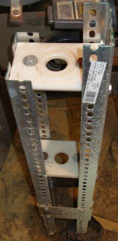
Rotator 3.0
The
rotator above was made of stamped galvanized angle stock from the home
improvement store (Menard’s). The bearings float on brackets and are made out
of slippery nylon-plastic like cutting board. After they were aligned, I
tightened them. They were cut slightly oversize with a hole saw and the rotator
was mounted below in a slotted hole arrangement to make alignment easier. This
rotator worked about as well as the first. Maybe less well. The flex in the
frame skewed the bearings and they worked more like brakes. Since the brackets
were made of aluminum and the frame of steel, this unit could not be welded to
hold it together more stiffly. During the year this rotator was installed, we
dashed the stucco on the house. The green buildup you see in the photo is
overspray. You can also see how some of the hardware rusted very quickly, and
some held up.
The
fourth version (below) has been in use for three years now and works well. I
was forced to give up on the TV rotator, so I bought a small Yaesu rotator and
built the frame around it. It is about twice as big as the previous one. A
friend of mine gave me a sheet of the decking he used in his snowmobile
trailer. It is similar to the cutting board material, but it’s ½” thick. The
frame was made from the same stamped galvanized angle stock, and was bolted
together as a prototype. Then I installed the rotator and built a sleeve to
adapt the mast size to it out of galvanized water pipe and other bits and
pieces to shim it to size. Than I removed the unit and welded it, removed the
nuts and bolts (to reduce weight) and painted the frame. I reassembled it, got
it rotating properly and installed it with my neighbor. This one has the long
side of the frame parallel to the house, as opposed to perpendicular in the
last version. This was intended to minimize any sagging in the future. You can
see I also added two more pieces of stock to hold it to the house. I inspect it
every spring and fall and it has held up well. When the weather is below zero,
or we have had freezing rain, it will sometimes refuse to rotate, but that
might be true with any setup.
Rotator 4.0 This was
taken sometime in 2008-2009
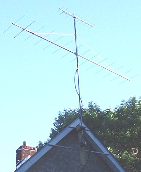
In
Fall 2010 I noticed that the 2 meter antenna was beginning to sag. The birds
had carried away the string I used to hold it up ( It is still the VB-214FM,
which has a terrible bracket in the middle) so I decided to go up and repair it
in an attempt to get a few more years out of it. One of the downsides of the
arrangement we have here is that it’s inaccessible in the winter due to snow. I
have a ladder that lays on the roof (an inverted v shaped thing that goes over
the peak) to access the antenna without causing too much wear on the shingles.
For
a ham living in the city with lots of wires everywhere, this is a good
solution. It’s about as tall as I can get it. Using the house rather than a
tower keeps the costs down. Not to mention, the feedlines are somewhat shorter
too. There are a few disadvantages though:
- It does cause wear
on my roof. I have had to replace the cap shingles right about where I’m
sitting. Luckily the ridge vent is under them, so the damage is minor.
- One can only access
the rotator and antennae certain times of the year (my personal rule is
that it must be above 50- so the shingles are not brittle).
- It is tough to get
antennae up there. You need help.
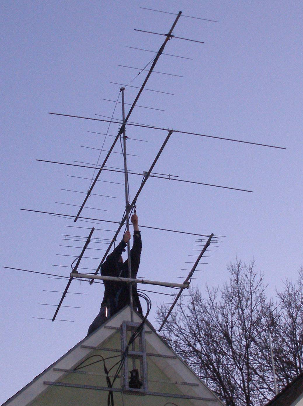
Left bottom: DS rover
yagi for 222, right bottom: DS rover yagi for 432, middle: DS 4 ele for 6m,
top: Hy-Gain VB-214 FM.