Cubic ASTRO B: a 100-125W 32 channel 2-24MHz
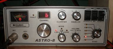
Cubic
ASTRO-B
After I received the radio, I tested it and it worked well, so I bought
a manual and located the PROM inside. The PROM was soldered to a carrier that
plugged into a socket on one of the boards in the front inside of the radio.
During my search, I located a slip of paper with the programmed frequencies and
settings on the PROM! What luck! The image below is close to actual size.

List of Programmed Frequencies
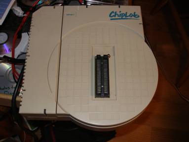
I then wanted to learn how to read and program it. I located a PROM
programmer and software and got it running on my PC. It was difficult to find a
programmer that would burn the Harris chip. I then removed the PROM from its
carrier so it could be inserted into the reader. That was somewhat difficult
and I wrecked some traces on the PROM holder (Cubic calls it a channelpak). The
programmer I have been using is a Data I/O Chiplab. This is what I got when I
read the PROM:
:1000000009090402050D00000F0F0F0F0F0F0F0F4E
:1000100004040601050D050104040601050D050192
:1000200004080201050E000104080201050E00018A
:1000300004070201050E000104070201050E00017C
:1000400004060201050E000104060201050E00016E
:1000500009040101050C000109040101050C00015E
:1000600007040001050C000107040001050C000154
:1000700009090900050D000109090900050D000124
:1000800006090900050D050106090900050D050110
:1000900004090900050D000104090900050D00010E
:1000A00009090909040D00020F0F0F0F0F0F0F0FA1
:1000B00001030008040D050201030008040D0502F8
:1000C00004070907040E000304070907040E0003D0
:1000D00004070807040E000304070807040E0003C2
:1000E00004060807040E000304060807040E0003B4
:1000F00004040707040C000304040707040C0003AE
:1001000004030707040C000304030707040C00039F
:1001100009090607040D000309090607040D000379
:1001200004050607040D000304050607040D00037B
:1001300006030607040D050306030607040D050361
:1001400006020607040D050306020607040D050353
:1001500008000607040D050308000607040D050343
:1001600001000507040D050301000507040D050343
:1001700009090904080D00030F0F0F0F0F0F0F0FD0
:1001800005020001080D000405020001080D00042D
:1001900006010600080D050406010600080D050409
:1001A000050208080F0D0005050208080F0D0005DF
:1001B000010007080F0D0505010007080F0D0505D3
:1001C000020800050F0D0005020800050F0D0005CF
:1001D000090909040F0D00050F0F0F0F0F0F0F0F67
:1001E000050206040F0D0005050206040F0D0005AB
:1001F000010204040F0D0505010204040F0D05059D
:00000001FF
Here’s what I think it says:
:100
00 – Channel number in hex
00 - ?
0 - ?
09 09 04 02 –
reverse this number and you get 2499. Take 2499 and add it to the desired
frequency (2500 KHz) and you get 4999. This formula is true for all of the
programmed frequencies below 5MHz. All of the programmed frequencies between
5MHz and 15Mhz equal 14999 when added to the value here- in reverse. Same is true for all of the programmed frequencies
above 15MHz. They equal 24999 when added to the reverse of the value. At least
I think this is how it works. This provides the KHz, any hundreds of hertz come
later from a different
05 –This is a value that indicates which
value receive freq
05 <4999
KHz
04 5000 to 14???KHz
08 14??? To 15???KHz
0F 15??? To 24999KHz
0D –
mode-
value mode
0C LSB
0D
0E CW.
00 - hundreds of
hertz. This is the separate
Value Hertz
00 000
05 500
00 band- 0-5. the ranges below
need to be refined:
Band
0 up to 3000 KHz
Band
1 3000 to 4500 KHz
Band
2 4500 to 7000 KHz
Band
3 7000 to 10000 KHz
Band
4 10000 to 15000 KHz
Band
5 15000 KHz and up
0F 0F 0F 0F 0F 0F 0F 0F – Transmitter frequency and band setting, same
pattern as receive.
4E – No room on programmer interface for this number. And the PROM works
without it.
I made a table of all of the values I wanted to program into the PROM. I
thought I would be able to load this text file at first. Later I learned I had
to thumb it in through Chiplab. To help me while I edited the file, I put the
column headings at the top of each column. This is just a different way to
break it down than I did above.
Except for the headers, this is how it looks in Chiplab (see below). The
values appear in each column twice, once for receive (left half) and once for transmit
(right half).
Column data (see above
for range of values)
Chan channel in hex
Diffinrvrse difference of the
VFO number and the desired frequency, in reverse
(four columns)
Vf which VFO to
use
Mo mode
Hz hundreds of
hertz in desired frequency
Bn band
chan diffinrvrse vf
mo hz bn diffinrvrse vf
mo hz bn ??
:10 0000 00 06 09 09 02 05 0D 00 00 06 09 09 02 05 0D 00 00 4E
:10 0010 00 04 03 09 02 05 0D 00 00 04 03 09 02 05 0D 00 00 4E
:10 0020 00 00 02 09 02 05 0D 00 00 00 02 09 02 05 0D 00 00 4E
:10 0030 00 07 01 08 02 05 0D 00 00 07 01 08 02 05 0D 00 00 4E
:10 0040 00 09 09 04 02 05 0D 00 00 09 09 04 02 05 0D 00 00 4E
:10 0050 00 04 00 00 01 05 0D 00 01 04 00 00 01 05 0D 00 01 54
:10 0060 00 03 00 00 01 05 0D 00 01 03 00 00 01 05 0D 00 01 54
:10 0070 00 02 00 00 01 05 0D 00 01 02 00 00 01 05 0D 00 01 54
:10 0080 00 09 09 09 09 04 0D 00 02 09 09 09 09 04 0D 00 02 A1
:10 0090 00 09 06 06 09 04 0D 05 02 09 06 06 09 04 0D 05 02 A1
:10 00A0 00 03 05 06 09 04 0D 05 02 03 05 06 09 04 0D 05 02 A1
:10 00B0 00 03 03 06 09 04 0D 05 02 03 03 06 09 04 0D 05 02 A1
:10 00C0 00 08 02 06 09 04 0D 05 02 08 02 06 09 04 0D 05 02 A1
:10 00D0 00 06 09 05 09 04 0D 05 02 06 09 05 09 04 0D 05 02 A1
:10 00E0 00 04 02 08 07 04 0C 00 03 04 02 08 07 04 0C 00 03 AB
:10 00F0 00 01 02 08 07 04 0C 00 03 01 02 08 07 04 0C 00 03 AB
:10 0100 00 09 01 08 07 04 0C 00 03 09 01 08 07 04 0C 00 03 AB
:10 0110 00 04 01 08 07 04 0C 00 03 04 01 08 07 04 0C 00 03 AB
:10 0120 00 09 00 08 07 04 0C 00 03 09 00 08 07 04 0C 00 03 AB
:10 0130 00 04 00 08 07 04 0C 00 03 04 00 08 07 04 0C 00 03 AB
:10 0140 00 09 09 07 07 04 0C 00 03 09 09 07 07 04 0C 00 03 AB
:10 0150 00 04 09 07 07 04 0C 00 03 04 09 07 07 04 0C 00 03 AB
:10 0160 00 08 06 07 07 04 0D 00 03 08 06 07 07 04 0D 00 03 AE
:10 0170 00 07 06 07 07 04 0D 00 03 07 06 07 07 04 0D 00 03 AE
:10 0180 00 06 06 07 07 04 0D 00 03 06 06 07 07 04 0D 00 03 AE
:10 0190 00 09 03 07 07 04 0D 00 03 09 03 07 07 04 0D 00 03 70
:10 01A0 00 03 00 07 07 04 0D 00 03 03 00 07 07 04 0D 00 03 79
:10 01B0 00 02 00 07 07 04 0D 00 03 02 00 07 07 04 0D 00 03 79
:10 01C0 00 09 09 09 04 08 0D 00 03 09 09 09 04 08 0D 00 03 D0
:10 01D0 00 07 05 06 00 08 0D 05 04 07 05 06 00 08 0D 05 04 09
:10 01E0 00 09 09 09 09 0F 0D 00 05 09 09 09 09 0F 0D 00 05 09
:10 01F0 00 02 04 08 06 0F 0D 00 05 02 04 08 06 0F 0D 00 05 C1
:00000001FF
At any rate, I think I had enough data to try burning a chip. The plan
was to try a Signetics 82S131 chip that is supposed to be a substitute for the
Harris chip. Harris ones are available on eBay for triple the money, no
guarantee and a warning from the seller that they may have some programming on
them. No thanks.
Here is the programmer:
I had originally edited a text file of what I had extracted from the
PROM that came in the radio. Trying to get the device to recognize any of the
edited files didn’t work at all. After groping around, I learned that you have
to edit the data directly in the program. On

There are two full screens to program. There’s nothing fancy about it,
no copying and pasting to speed it up. I programmed 32 frequencies to test the
burning process and the radio. These included several Navy and Coast Guard
frequencies (for the
Work progresses on this radio. While testing my chip programming, I
noticed that the radio is off frequency. So I bought a service manual and dove
in. I wasn’t able to adjust the LO back to frequency. So I replaced it with an
Epson SG8002 Oscillator. See the picture on the right. I trimmed the other
oscillator to match the Epson’s output. The result is that when trimmed for 40
Meter frequencies programmed on my PROM, I am off on the 17 Meter frequencies-
a lot off.

Above is the front view with the top open. In the middle you can see the PROM on it's carrier. In the photo on the right, you can see the oven- someone has been in there before with the duct tape. The photo below is the board with LM7805 and oscillator

The next step is to study the manual for the correct method of chip coding
and revisit the frequencies the oscillators should be set to. I bet I’ll need
to find a happy medium.