|
A Re-Manufactured Hammarlund SP-600 Receiver
***
YOU'VE GOT TO BE KIDDING! ***
When first asked if I were
interested in undertaking the restoration and overhaul of
this receiver, and that it was a "basket case", I informed the owner
that it was probably best to use the components as spare parts for his
other SP-600 receiver (a military R-274C/FRR version).
However, when he told me
that if I undertook the task, I could have my pick of the litter, I
decided to give it a shot. I felt that 50 years of
home-brewing and repairing radio equipment of all genres gave me a good
background for the task.
Right from the start I told
the owner that I preferred to keep the factory wired unit as my own,
and this was fine with him. He wanted some modifications
performed on his receiver anyway, and these were easiest to perform
during the construction phase. The modifications
performed are listed at the end of this article, followed by PICTURES
of the COMPLETED unit. There were NO pictures
taken showing it's condition when it arrived here because I didn't have
access to a good camera.
Later, upon seeing the
actual unit I nearly changed my mind. The set was an empty
aluminum chassis, all the tube sockets, IF transformers, terminal
strips etc were in boxes and plastic bags. A clean and shiny
chassis, but bare none the less. The only parts installed on
the chassis were the power transformer and two filter chokes.
A local ham friend of mine
saw the receiver in this state and laughed out loud. Another
friend wasn't even 'that' kind and told me in no uncertain terms that I
was crazy to undertake such a task.
Luckily, ALL
vital components and necessary hardware (brackets, spacers, terminal
strips etc), except for the S meter were among the bags and
boxes. The
resistors and capacitors needed for the construction of the receiver,
as well as overhaul of the factory wired unit were provided by the
owner of the receivers.
The front panel was
unattached, as was the RF deck. The RF deck (big square metal
box in the center of the receiver) was the one bright spot in the
entire receiver. It was essentially intact and unmolested, with all
turret coils etc installed.
To make sure that the
overall project was worth doing, the RF deck was the first item to get
inspected, overhauled and recapped. Without a good RF deck
the receiver would be worthless. After it was recapped and
some mechanical cleaning and adjustments made the unit actually had a
smoother tuning mechanism than the one in my personal SP-600.
This was encouraging.
***
THE PREPARATION ***
At this point all the
components were prepared and cleaned up. Solder and old wires
were removed from the tube sockets, IF cans, terminal strips
etc. All parts that were to be recycled were examined for
damage. Needed components like resistors, capacitors, various
colors of wire etc were procured (provided by the owner).
Then all the
BBOD's (Black Beauties of Death) and out of tolerance
resistors etc in each IF can, BFO can, Second Mixer can and so forth
were replaced. The existing Mica capacitors were left in
place. The cans were serviced at this point so that
they could be dropped into the chassis without having to stop and
service each one during construction, possibly missing a BBOD.
***
RECONSTRUCTION BEGINS ***
Finally we were ready to
begin the actual re-construction process of this old
boatanchor. To help this go smoothly I first printed the
military TM11-851 manual and put it in a binder. This is an
excellent resource with all the schematics, parts lists and even
drawings showing actual component placement and wiring. Not
your usual skimpy little instruction manual.
All the tube sockets were
installed with their proper orientation, with at least one ground lug
for each. The power supply was wired and all filament and B+
distribution lines run before any small components were
installed. Any tube socket pins that were tied directly to
ground were grounded along with the center ground pin. Most of these
grounds were NOT soldered at this time. This preparation made
it much easier to neatly route the wires in cable harness form, using
Tie wraps as guides to keep the wires in order.
After the power supply was
wired, the audio section, comprised of the 6V6 and 12AU7 tubes was
wired. From this time on the wiring pattern basically
followed signal flow, starting with the second mixer/455KC IF gate
tube, through the IF strip from the first to last stages, followed by
the detector and AGC sections.
Special care was taken to
insure that all proper wiring practices were observed so as to
eliminate any possibility of instability. In wiring the IF
strip, the side panel was removed and the Bandswitch was NOT installed
until all IF stage wiring was completed and checked for accuracy and
proper continuity, TWICE. It is much easier to
work on the IF strip without the switch and side panel in place.
After all the basic chassis
wiring was completed it was time to consider installing the RF deck
into the main chassis. This needs to be done BEFORE the front
panel is mounted. All wiring to the front panel up to this point was
done by laying the panel up against the front of the set, putting the
switch or control in it's proper place and wiring it up so that the
leads would be of correct length/routing. Then the controls were
allowed to "dangle" by their leads. By bundling and tie
wrapping all the wires into a harness, most of the parts remained in
place until final assembly.
All new power connecting
wires were installed on the RF deck. There
was one glitch at this point. The cover on the
RF deck said it was version JX-14, which should have had 7
wires. However, this one only had 5 wires! Pulling
the tube module out of the deck again disclosed that this was NOT a
JX14, so I went ahead and wired it as a 5 wire unit. I'd
already mounted the power supply resistors for a JX14 and these were
just left in place as a bleeder resistor.
After resolving the RF deck
version dilemma, installation of the RF deck went well with no further
problems. The front panel was installed along with front
panel controls and switches. Shaft couplers were installed on
the BFO, Bandwidth and Xtal Phasing shafts and the knobs
installed. NO S meter has yet been installed as the owner
wants to make a scale for the generic meter he chose to use.
***
IT'S LOOKING LIKE A RADIO NOW ***
At this point the wiring of
every tube, transformer, control, terminal strip and switch were
checked for errors, TWICE.
A few connections which had been intentionally left unsoldered were
soldered, after ascertaining that no further work was needed at that
location (mostly grounds and B+ and AGC lines etc).
All tie wraps were cinched
up tight and additional tie wraps added to make for nice, neat wire
bundles. Routing of all wires was checked for any pinched or damaged
wires.
***
CHECK THE TUBES ***
The owner had provided all
the needed tubes for the receiver, along with some extras.
Some were new in boxes, but most were used tubes, either in boxes or
baggies. Since an untested tube is an unknown liability, and
this set hadn't played since the last millennium I wanted to be sure I
had good tubes.
So, I fired up the Hickock
800 A and tested each and every one. It's a good thing I
did. I ran into a number of very bad tubes, some weak and
some shorted etc. One brand new 6BE6 had a dead short!
***
POWER ON TESTING BEGINS ***
Then all tubes were inserted
into the unit, EXCEPT for the 5R4 rectifier. The radio was
plugged into a variac and brought up to about quarter Voltage so that I
could check the bias (modified with Silicon rectifiers) and filament
circuits. Since that didn't let the smoke out of anything I
went ahead and applied full power. The bias supply was
correct and the tube filaments lit.
So then I got brave and
plugged in the 5R4 B+ rectifier tube. With a Voltmeter
monitoring the B+ line and a set of headphones on my head, I gingerly
turned on the power (NO partial Voltage this time). The
Volume control was turned all the way down and I didn't even hear a
"hum".
Turning the volume control
up the receiver still seemed to be dead. OH NO!
However, touching the center pin of the volume control with my finger
showed that the audio stages were working as expected, but there was
absolutely NO RF noise. Turning the BFO on did create a hiss,
indicating that the BFO and product detector (another modification) was
working. But there were absolutely no stations, not even the local
blockbusters.
***
TIME TO TROUBLESHOOT ***
Well, nobody said this was
going to be easy, but I had hoped to at least hear something.
I tested the Voltages on ALL of the IF tubes etc. Every
indication was that the IF section was dead, but all Voltages checked
good and I couldn't find any wiring errors!
Time to dig out the test
gear. But first I decided to take the 455KC output from my
SP-600 (on an "Oldies" station) and use it as a known signal source to
see if I could track down the dead stage. Starting at the
detector and working my way back through the IF strip, I was able to
hear the "Oldies" through the entire strip, but couldn't hear any
difference or increase in signal strength as I progressed through more
stages.
Hmm. What's going
on here. Then I thought, hey, the signal from the receiver is
probably too strong and overloading the IF strip. So, I
dropped the RF gain of the working receiver, turned the Audio gain way
up, then turned the RF gain down further until I could just barely hear
the station in the test receiver.
***
NOW WE'RE GETTING SOMEWHERE ***
This time, when I started at
the detector and went back stage by stage I could hear the actual
difference each stage made. I also peaked each IF transformer
as I went through the set. MOST of the IF adjustments were
way off, and not by the same amount or in the same direction.
After going through the IF
strip in this manner I disconnected the signal from the test
receiver. Upon again checking with an antenna,
VOILA! I had radio stations
Checking all the bandwidth
positions showed that it was functioning as it should and the receiver
was ready to receive a full alignment and burn-in. But first
the radio was run for several hours to make sure that nothing would die
an early death.
A thorough alignment was
completed with no unforeseen problems developing. Most of the
bands were fairly close to begin with (Indicating the previous owner
didn't have "Screwdriver-itus", at least in regards to the RF
deck). The two lowest bands were "dead on".
***
MODIFICATIONS PERFORMED ***
As I mentioned at the
beginning of this article, the owner wanted a number of modifications
on the receiver. Here is a description of what was done.
1. Eliminate the
Send/Rec, Limiter and Meter switches to allow use of these for other
purposes.
2. Eliminating the
limiter and AF meter function allowed the 6AL5 tube and associated
circuitry for these functions to be eliminated.
3. The 6AL5 Bias
rectifier was eliminated and 1N4007 silicon diodes wired in it's place,
on a terminal strip mounted to the rear panel where the bathtub
capacitors had been mounted. Also, the bathtubs were replaced
by 22uF/160VDC capacitors mounted to another terminal strip adjacent to
the first.
4. BFO:
For some reason the 7 pin BFO tube socket hole had been re-punched for
a 9 pin socket. So, a 6U8 tube was used in that location for
the BFO and BFO buffer stage. Using the Pentode side of the
6U8 allowed the elimination of the 6BA6 factory buffer
stage. There is a 150 Ohm resistor in the Cathode
of the Buffer stage, bypassed with a .1uF capacitor. A .5mH RF choke
was used in the plate of the buffer stage with parallel capacitors to
comprise a low "Q" tuned circuit at 455KC. The Buffer
is coupled to the 6BE6 product detector through a .001uF
capacitor and 30K "BFO Injection potentiometer.
5. Product
Detector: A conventional 6BE6 product detector circuit was
used. IF signal for this stage was tapped from the same point
that feeds the IF driver stage grid as I felt the signal level at the
output of the IF driver would be stronger than was needed and would
overload the product detector. The DPDT Mod/CW switch selects
either Product or AM detector on one side while the other side applies
the regulated B+ to the triode of the 6U8 tube (BFO).
The unused limiter switch was used to select the Slow AGC
capacitor (.22uF), formerly switched by the Mod/CW switch.
6. S Meter
Circuit: As the owner wished to use a generic 1mA meter
movement for his S meter, an Amplifier just for this function had to be
created. This was installed in the tube socket normally
occupied by the BFO buffer stage. It uses a 6C4 triode tube
and is the same circuit that is used in the Hammarlund HQ-180
receiver. Being a bridge circuit there are two controls, one
to zero the meter and another to control the meter sensitivity.
7. Pre-Xtal filter
IF output: The owner wanted to use a panadapter with this
set So, a 6.2pF capacitor was connected to the plates of the
455KC gate/2nd mixer stage and connected to a terminal strip adjacent
to the tube to allow the connection of a coax cable to the rear panel
SO-239 IF output Jack. NO IF CATHODE FOLLOWER was installed
in this receiver, leaving one side of the 12AU7 unused.
8. An IF gain
control was added to the first IF amplifier stage, as shown in the
military modifications supplement. This was mounted adjacent
to the IF amplifier tube where somebody had drilled a hole for some
unknown reason (Each of the IF stages had such a hole drilled, suitable
for a control).
9. A single point
"Star" grounding system was used for the power supply, in the vicinity
of the Filter chokes. Shielded wire was run from the
Headphone winding of the output transformer to the headphone jack, with
a "single point ground" located at the headphone jack. This
made for a VERY quiet audio stage with NO hum whatsoever audible in the
headset.
***
SO, HOW DOES IT PLAY? ***
In comparing it against the
factory wired unit that I have here, it was very difficult to hear any
difference at all between the sets, either on strong local broadcast
stations OR weak shortwave stations. HOWEVER, there is NO hum
in the headset, and, in listening to SSB or CW the
improved BFO and product detector circuitry were clearly superior to
the original Hammarlund circuit! Of course that does nothing
for the fast tuning rate on the higher ham bands. The
smoothness of the tuning mechanism is definitely much better in the
re-manufactured unit."
The owners remarks when he
picked up the receiver? "Man, that's
really clear sound"!
FINALLY,
I WOULD LIKE TO THANK ALL THE KIND FOLKS WHO GAVE ME ADVICE ON THE
BOATANCHOR AND HAMMARLUND MAIL REFLECTORS. IT MADE THE JOB GO
A LOT SMOOTHER THAN IT MIGHT HAVE OTHERWISE GONE!
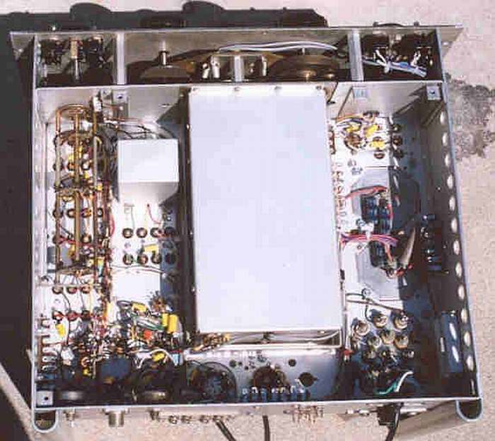
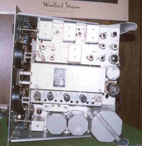
Full Under Chassis view
of completed SP-600
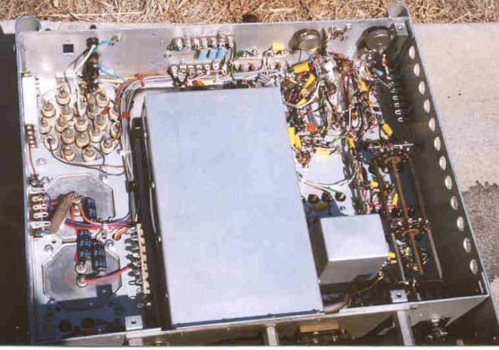
Another full Under-Chassis view
of completed SP-600
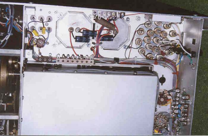
Close-up Under Chassis
view of Power Supply section
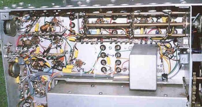
Close-up Under Chassis
view of IF Strip
Top View of entire completed SP-600 Receivr
Melt
Some Solder!

|