|
The PA0LQ Narrow Audio Filter
This article describes the construction and use of a very narrow, fixed
frequency audio filter suitable for DXing NDBs (Non Directional Beacons) under
the most difficult of conditions. It was designed by PA0LQ and
improved by Roelof, PA0RDT. Roelof kindly assisted me with my unit
and has granted me permission to post it here.
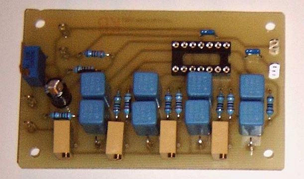
CAVEAT: Because of the extremely narrow bandpass of this filter, the receiver that it is used with MUST be able to be tuned in steps narrower than the bandwidth. That is, if it's aligned for a 6 Hz bandwidth, the tuning step of the receiver MUST be less than that, ideally, in 1 Hz steps! This is not a step by step "how to" primer for the person with no electronics experience, but rather a presentation of the circuit along with construction and alignment tips. It is assumed the builder has some knowledge of electronic construction practices. You have options as to whether to breadboard it on what is called a "perf board", use the ugly dead bug construction, or make a circuit board for it. Roelof very kindly sent me the circuit board etc to build mine (the one you see in these pictures), but I believe that he had a very limited number of these. Only the actual filter is covered in this article, you will need to add a small audio amplifier capable of driving your headphones on the output. I used the one available here. . . http://g4oep.atspace.com/headamp/headamp.htm. In my case it is the small circuit board mounted on the back panel of the audio filter. OR! You may use the audio amplifier project that I have posted here. . . lm380.html ALIGNMENT AND CONSTRUCTION TIPS: 1. You CAN align all stages to exactly the same frequency, but I found my filter was too narrow to be practical at that bandwidth (about 3 Hz bandwidth). 2. It isn't quite symmetrical on the upper frequency vs. lower frequency. I found that for a symmetrical roll-off, I had to favor the low side just a tad (about 1-2 Hz). After doing that it was very well matched between the low and high frequency side. Here is the frequency response of the one I built, centered on a 500 Hz center frequency (CW Pitch). 500 Hz Filter, 6
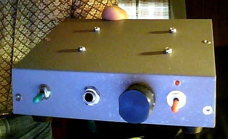
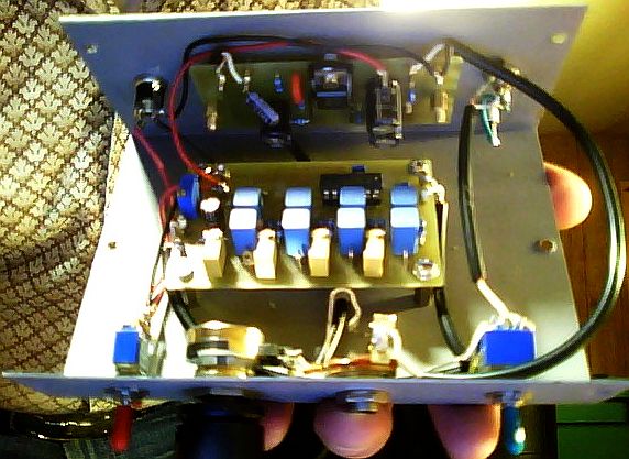
Hz Bandwidth (3dB points). 3. Tuning of the multi-turn pots is very critical. Once you have them tuned, I suggest you lock them down with a dab of your wife's fingernail polish (don't use anything you can't "break" later in case you want to retune it). 4. I did not have an audio generator with accurate, 1 Hz frequency steps. Instead, I used my FT-2000 transceiver in CW mode, tuned a local station and tuned that in 1 Hz steps to generate the required tones (checked with a counter). It worked well. 5. Observe GOOD construction practices, keeping inputs away from the outputs, shielded audio cables etc. Failure to do so may cause the unit to go into oscillation! 6. You may want to adjust the gain to provide a "boost" when the filter is engaged. I have mine set so that a 500 Hz 'tone' is 10dB louder when the filter is engaged vs. when it isn't. I chose that as it works well with my set-up here. Also, using as little volume INTO the filter as possible will improve performance. This is where having a headphone amplifier with volume control after the filter really helps. . . 7. In use, you will have to re-think your DXing strategies. You CANNOT tune quickly through a wide bandwidth, but rather tune very slowly in the vicinity you anticipate hearing an NDB. I.E. Around the 1KHz frequency assignments, +/- roughly 50 Hz, 400 Hz Offsets +/- 50Hz and so forth. Slow tuning, close listening and patience is the key here. With practice this filter will allow you to detect a weak ID just a couple Hz or so from an adjacent carrier! Having said all that. Here are the pictures of my finished unit. The pictures of my unit were taken with the web-cam in my Acer Laptop (back-up computer) and so aren't very good, but you can get the idea.
Melt Some Solder!

|