RF Chain Construction
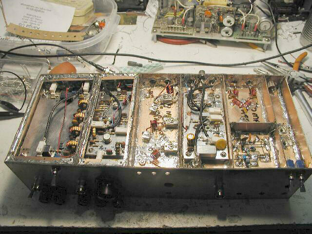
Here is the almost-completed RF chain. Note that in normal operation, these boards "hang upside down" that is, right now the SA is inverted, with the
bottom up. From left to right, the various sections are:
- Power and in/out switch for 10MHz crystal calibrator oscillator (note RCA jacks through floor, in/out of first 20dB pad...all input to the SA
comes through this switch, either from the main input or from the calibrator)
- (Top) 70MHz Low Pass Filter (Bottom) 10MHz crystal calibrator
- First Local Oscillator (with VCO) and Mixer; up converts incoming signal to 110MHz
- 110MHz Bandpass Filter (note the mica compression trimmers and three holes in front panel (more about this in the next section)
- Second Local Oscillator and Mixer; down converts 110MHz IF to 10MHz
- 10MHz Resolution Bandpass Filter (only 300KHz filter currently installed)
Note also that the "lips" or cover shelves have already been installed on the 2nd LO/Mixer and 10MHz BP, and holes drilled for screws. These two
circuits have already had their covers installed, but have been removed in this photo for testing.