Enclosure Construction
|
|
|
|
|
|
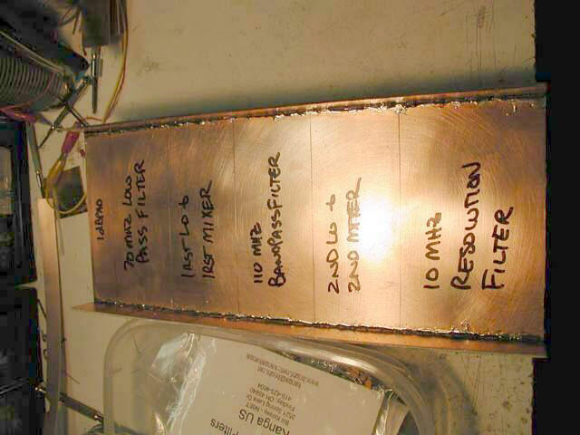
Here are the RF chain sections before the walls were installed. After looking at Sam Billingsley, AE4GX's SA, I also realized that I needed to add a 10MHz crystal calibrator and a means of switching it in and out of the RF path. I used the section labelled "1dB Pad" in this photo to house the switch and cabling. At that point, I had already built the 70MHz Low Pass filter, and it only used half of the section. The remaining half was the perfect size (and place!) to put the oscillator (a simple Colpitts with a pad attenuator to get it to about -10dBm, built on a NOGANaut PCB with the Pi pad instead of a Pi filter).
A 2.5" piece of RG-174 shielded wire connects the input BNC (which comes into the 20dB filter exactly opposite the section labelled "1dB Pad") and an RCA plug (fully shielded all around the plug). This plugs into an RCA jack in the floor between the two sections. On the switch section side, another piece of RG-174 connects from the jack to one side of a single pole, double throw switch. The other side of the switch connects to the 10MHz crystal calibrator oscillator output. The center conductor connects to a second RCA jack/plug combination in the floor via RG-174 and then on the the 20dB in/out switch.