The Frequency Meter/ Keying Monitor
This piece of equipment is a necessity for all early amateur stations. Regenerative receivers of that era were prone to overload, and it is totally impossible to be able to listen to your sending wave on the station receiver. Also, the dials on the transmitters and receivers of the era weren't calibrated as today's radios are, so some calibrated means of finding your frequency is a necessity.
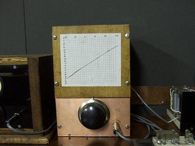
My frequency meter was patterned after a 1929 meter published in QST. Although their meter used a type 199 tube, I opted to cheat and use a number 30 tube instead, although the remainder of the circuit is identical. It is basically a single tube regenerative detector housed in a shielded case. This allows the transmitter to be heard without overload. The dial is calibrated against the graph above the tuning dial. The dial is a National Velvet Vernier, and it tunes the entire 80 meter band with a little overlap on each edge.
The basic circuit is a split hartley oscillator. Feedback is fixed, and is set to oscillate strongly. The unit runs off of 2- D cells and 3- 9V for the plate. The headphones plug into the cathode return of the B+ supply. I use a modern stereo 1/4 inch phone jack to make the connection. The tip of the plug connects to the filament battery, the ring connects to the filament of the tube, and the shield hooks to the B-. This way, the filament and plate supply are disconnected when the headphone jack is removed.
In this station, I have a DPDT knife switch that allows me to switch the audio amp input between the monitor and receiver. One side of the switch energizes the filament, the other side hooks up the audio.
Back