Moxon Mania!!!
James PalmerW7JMP
Go Home
This article documents the design and construction of my four band Moxon beam. What radio amateur hasn't dreamed of owning a beam? This my account of how I
got an HF beam on the air through research, design, and experimentation.
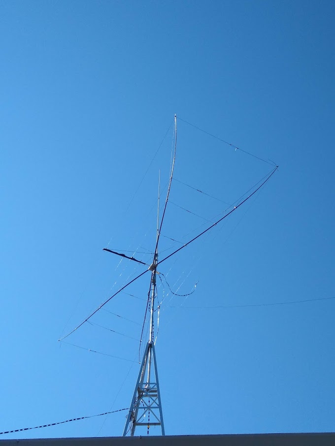
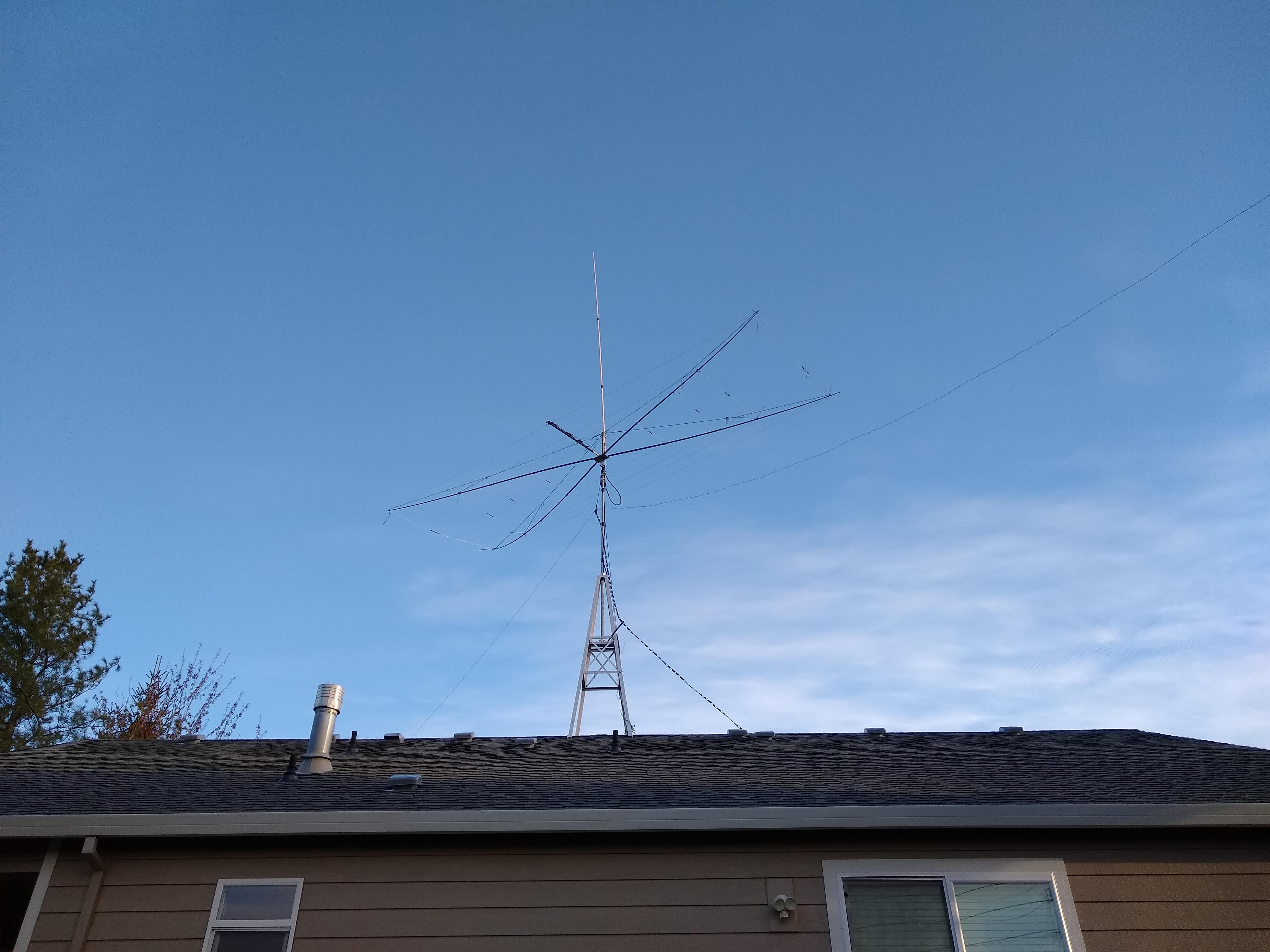
Fig 1. - Completed 4 bander Moxon beam mounted atop the rooftop tower.
Design Goals and Decisions
When I installed my rooftop tower, I had a rotary beam in mind. The top of the tower is just high enough to be about a half wavelength on 20 meters, and propagation is most consistent on 20m at this point in the solar cycle, so the beam needed to support 20 meters at a minimum. Given the limited space for antennas and the effort I would be putting into the project, additional bands would be very nice to add.
I evaluated how a full-size Yagi, Moxon, or Cubical Quad would perform vs. the effort and available space, and decided that although the expected gain of a full Yagi or Quad would be higher, the cost, weight, and size would be more than I wanted for an initial beam project. Hence a Moxon rectangle. I drew inspiration from these references:
Based on the literature review I ended up with these specific design features:
Computer Modeling
NEC model source code for the final configuration. All modeling was performed using 4NEC2. The code is based off of Cebik's formulas and code that came with NEC, where I added elements for each of the additional bands as well as a transmission line between elements. It ended working out that designing the 20/15/10m elements for the single-band Moxon dimensions works out, as discussed in reference [1]. However, 6 meters as-is does not work, and has to be scaled to the free-space dimensions for 43.4 Mhz.In references [1] and [2] I wondered why the feed was from the "outside in". It seems the impedance matches are better due to the stub detuning of the additional feedline on the higher bands, but it is less of an issue on 20 meters. I looked at this using the NEC modeling, comparing "inside out" to "outside in".
See Figures 2 - 5 for patterns for each band. Only 20 meters looks like a simple Moxon radiation pattern. I tried a variety of parameter optimizations on tip-spacing, shifting position.
I ended up back at the starting point of the basic single-band Moxon dimension. 15 meters, due to the 35 feet antenna height,
has the large lobe pointing straight up but still has a good low-angle lobe. 10 and 6 meters are what they are!
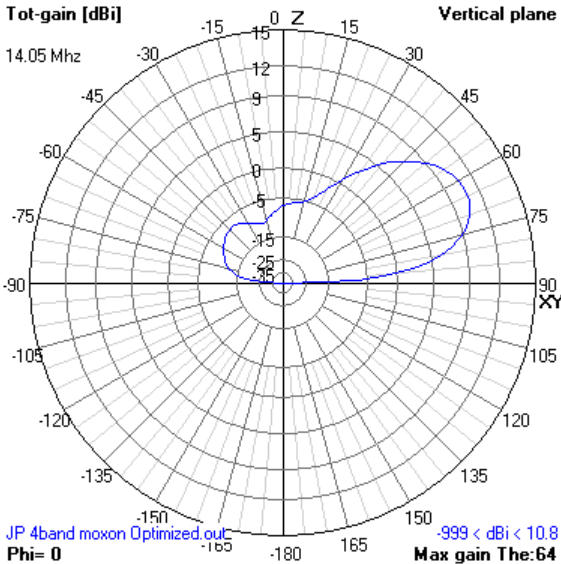
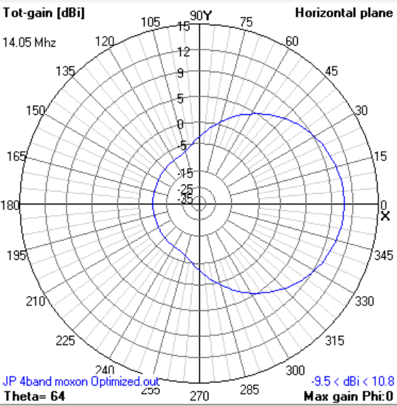
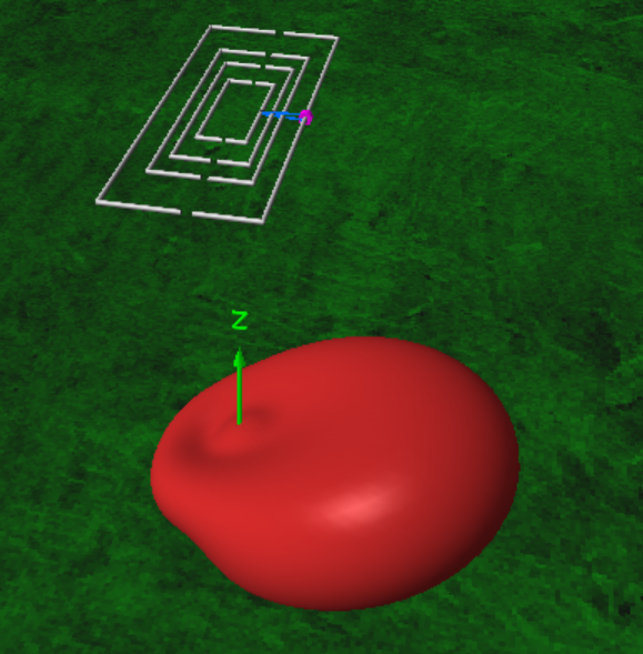
Fig 2. - 20 meter patterns.
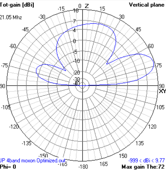
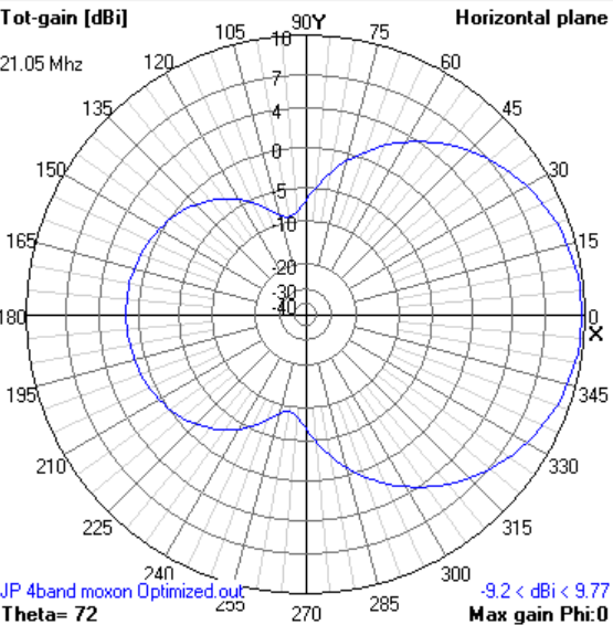

Fig 3. - 15 meter patterns.
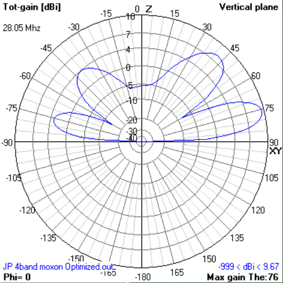
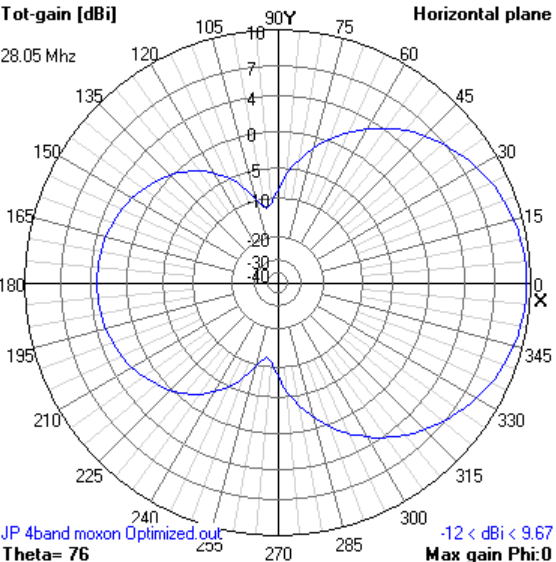
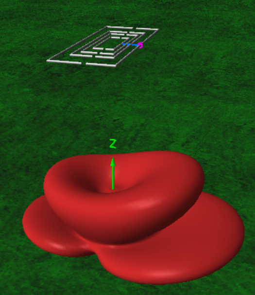
Fig 4. - 10 meter patterns.

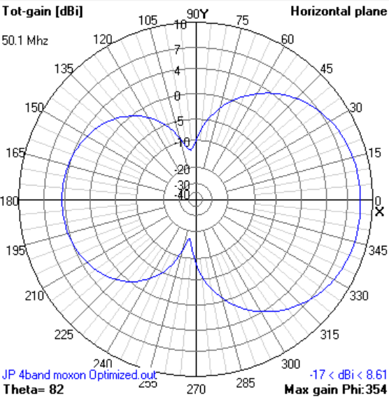
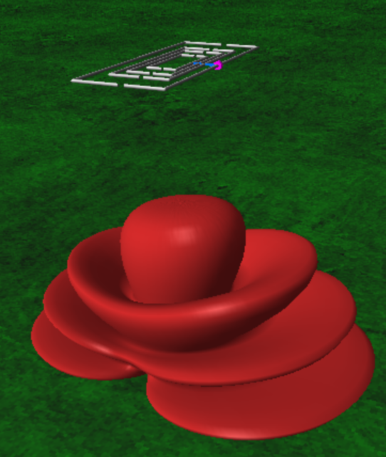
Fig.5 - 6 meter patterns.
The predicted SWR is good across 20m and 15m, though 10m and 6m will not have full band coverage and so you will have to choose the desired
sub-band for the best match to 50 ohms.
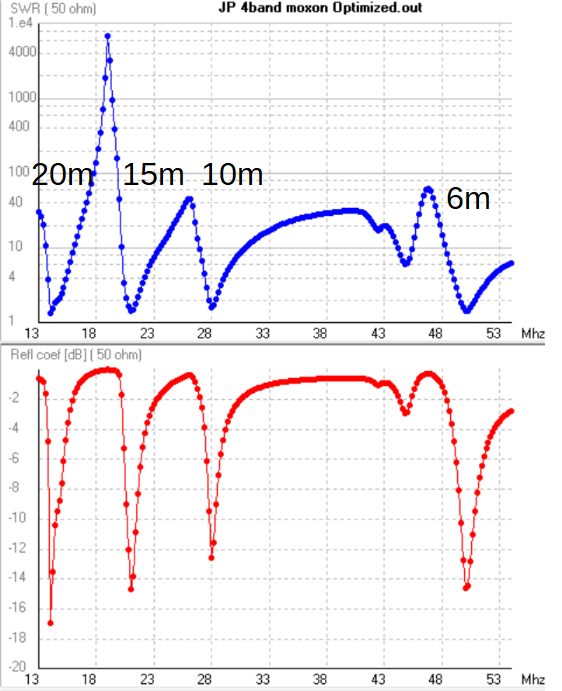
Fig. 6 - SWR and return loss plot from 4NEC2.
Dimensions and feeding
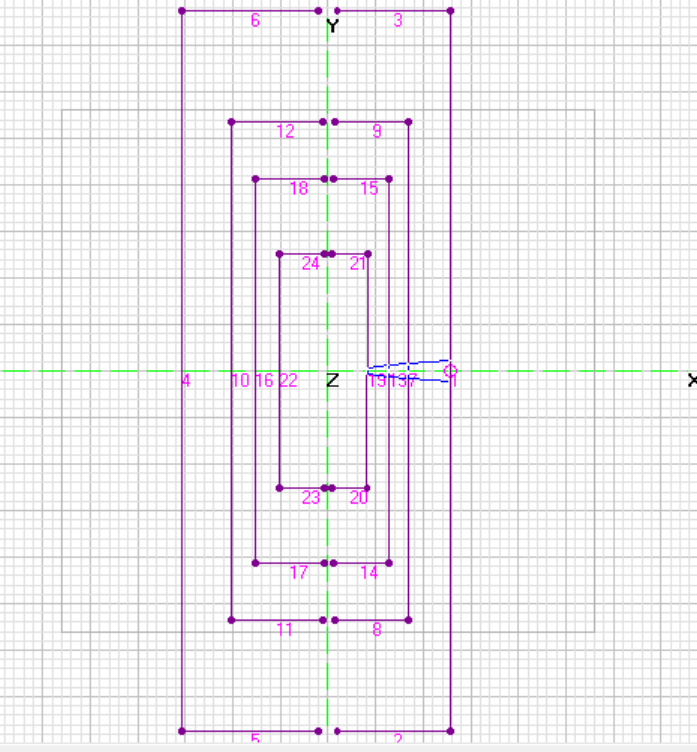
Fig. 7 - Diagram of the NEC model and its segments.

Table I - Wire lengths, made convenient for cutting.
The feed system is made of 50 ohm balanced line created by putting four strands of RG-8X together, as described in [1] and [2].
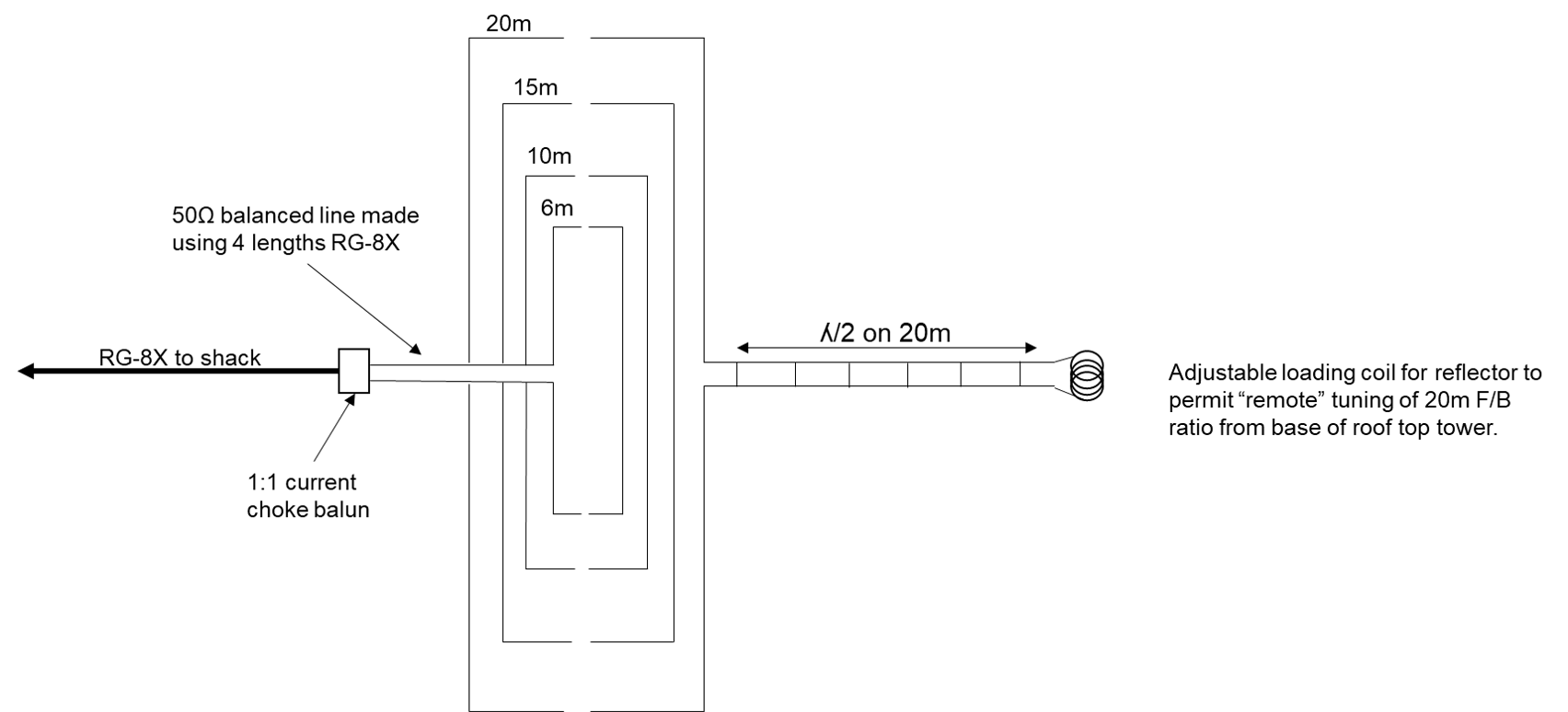
Fig. 8 - Connectivity of the Moxon elements. The 20m reflector tuning stub is discussed later in the article.
Collecting materials
Where possible common materials were selected. Specialized components include the hub and antenna rotator. All other components come from Home Depot, farm stores, and sporting goods outlets. You could choose to fabricate your hub out of tubing, a sturdy plastic plate, or aluminum yourself, but I determined the premade hub was well worth the price versus effort I put into fabricating it myself.
| Parts | Source |
| Hub | Ebay source. Comes with U-bolts |
| 20 ft Fiberglass fishing poles (4 pieces) | Bass Pro Shops. I bought B'n'M Black Widow crappie poles |
| 14 gauge wire | Insulated THTN wire from Home Depot . I ended up stripping to wire to avoid velocity factor corrections. |
| Driver-to-Reflector insulator | 4" Fiberglass electric fence insulators from Wilco |
| Hose clamps to keep spreaders from collapsing and to hold wire. | Home Depot |
| 3/8" vinyl tubing to run wire through. | Home Depot |
| 1/2" copper pipe to affix vinyl tubing to the hose clamp | Home Depot |
| Turnbuckles to tighten support ropes | Home Depot |
| Split nuts to lock wire into place | Home Depot |
| UV resistant camo rope | Home Depot |
| UV resistant black zip ties | Home Depot |
Assembly
In order to have a section of mast above the Moxon to mount the VHF/UHF vertical, I ended up drilling a 1.5" hole
through the hub plate. I just used a wood hole saw, and after a half-hour of drilling and a lot of WD-40 I ended up
with the needed pass-through hole and a dull hole saw.
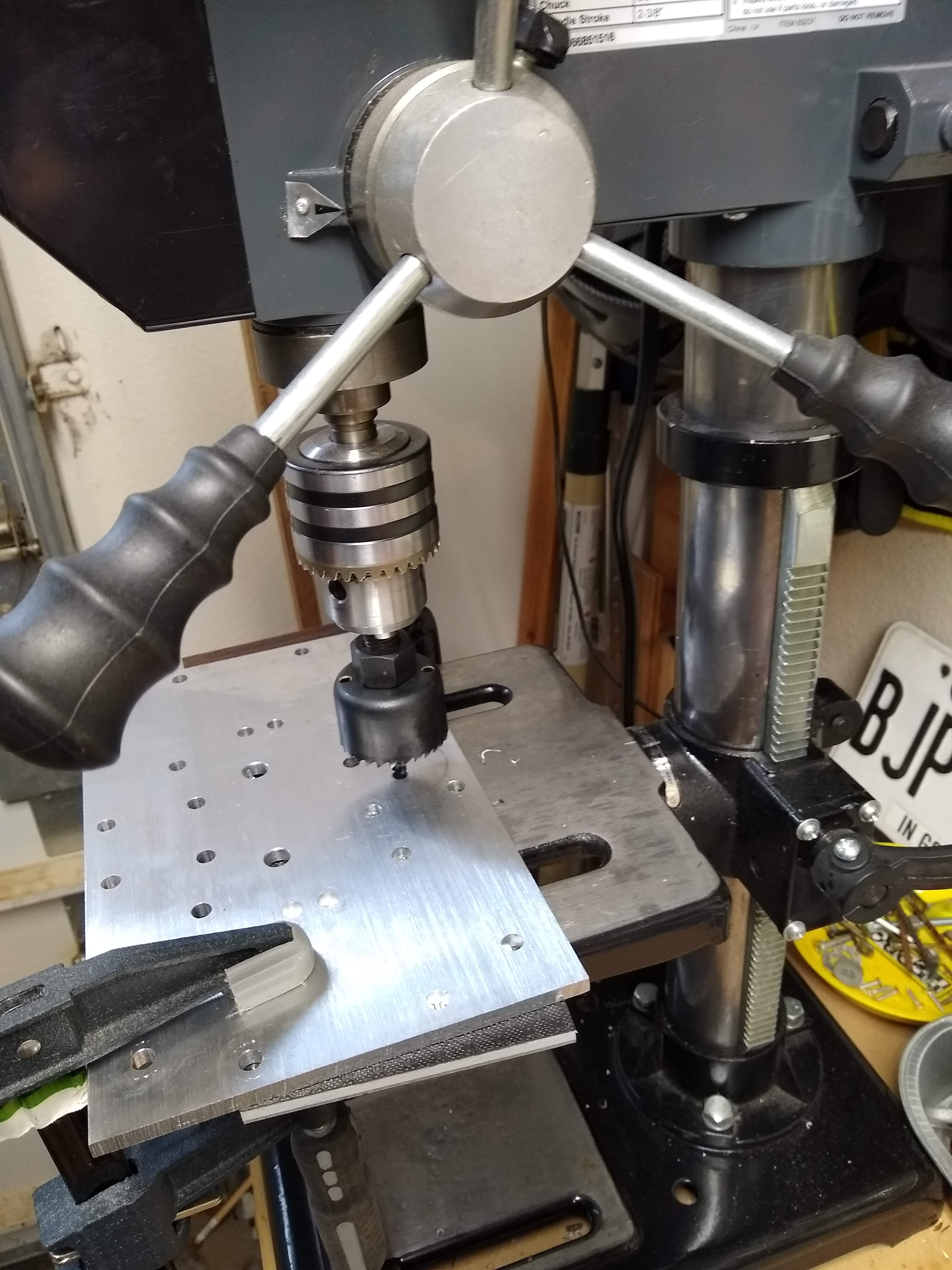
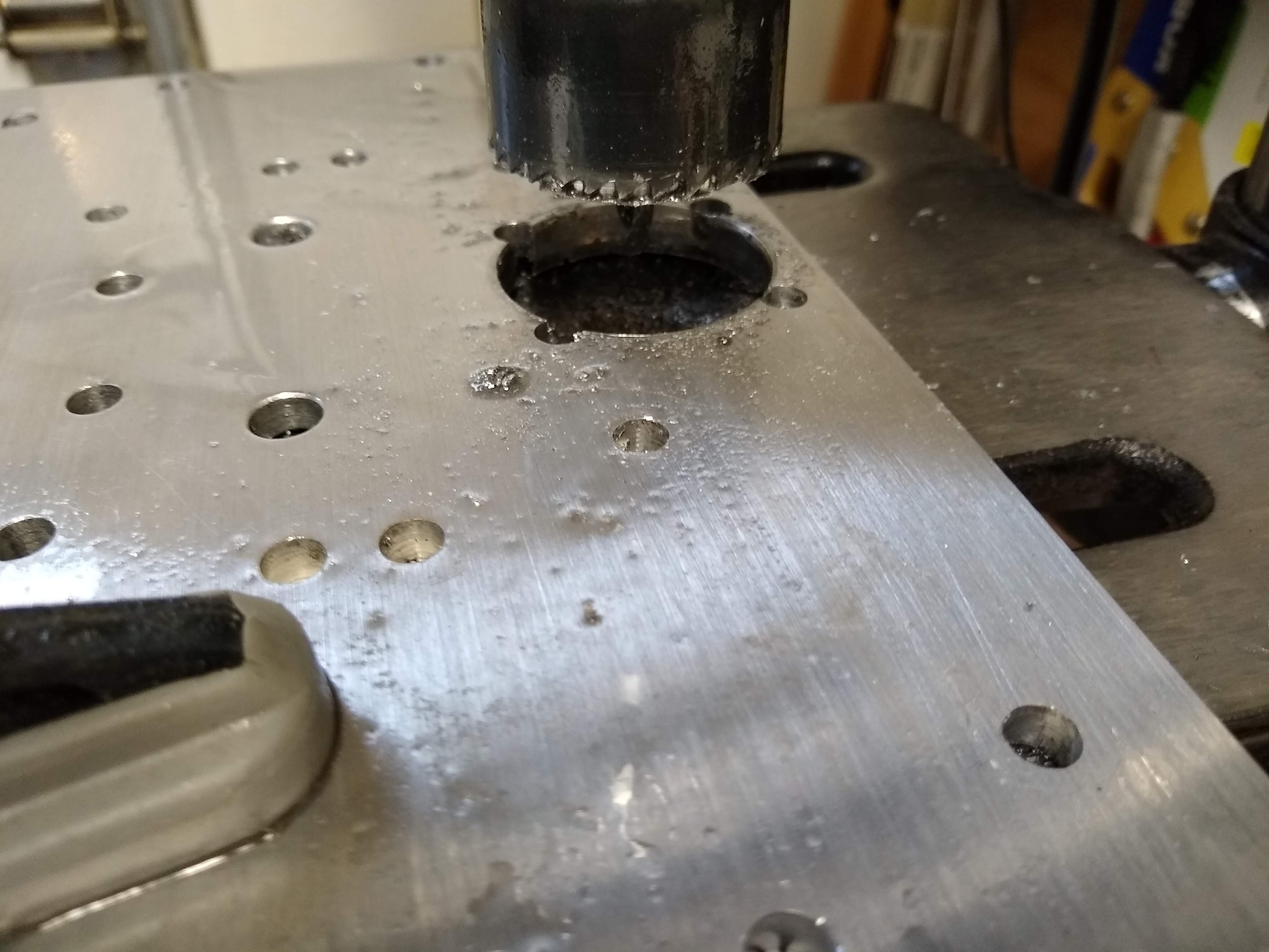
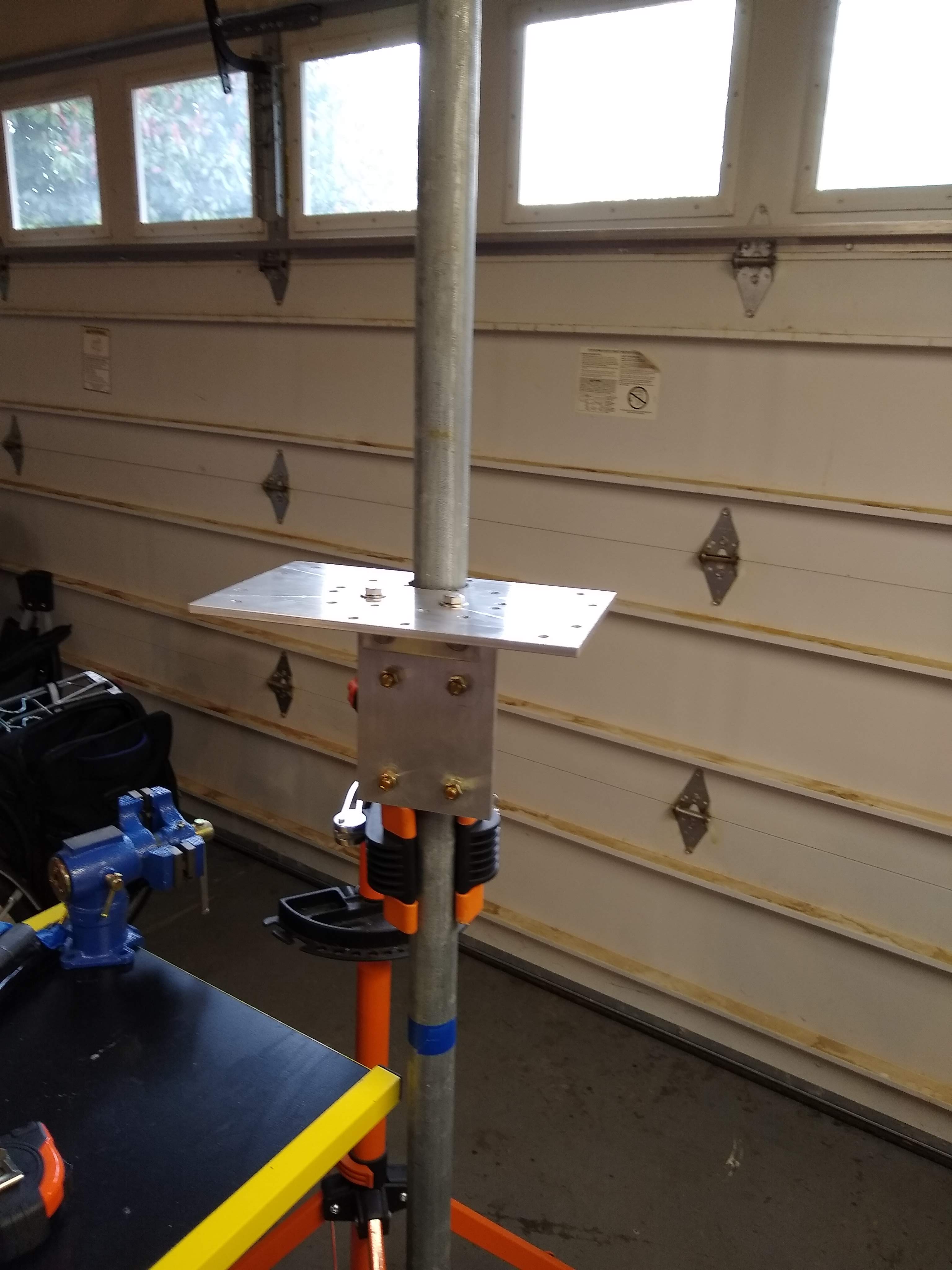
Fig. 9 - Cutting and assembly of mast to hub.
Mounting the fiberglass to the hub is shown in Figure 10. Since I bought 20ft long crappie poles, I didn't need the smallest and largest
diameter sections. This has a fairly tight tolerance and the u-bolts should not be overtightened such
that the fiberglass is cracked. Before raising it up lock-tite compound was applied to the nuts so it wouldn't vibrate loose in the wind.
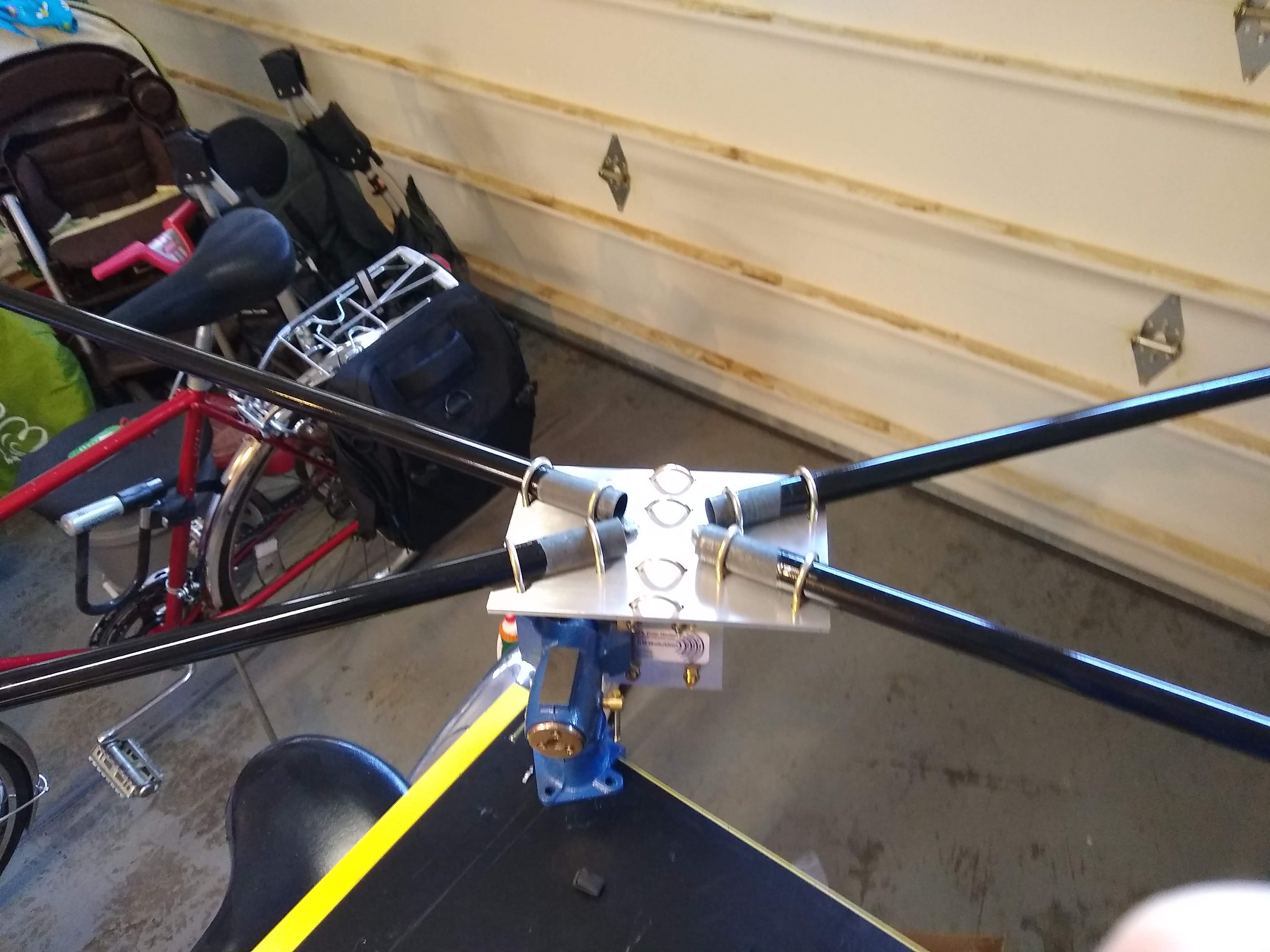
Fig. 10 - Mounting the fiberglass spreaders to the hub.
Shown in Fig. 11 I used the same technique recommended for cubical quads to attach the wires to the spreader poles, using a
vinyl tube, hose clamp, and a sleeve of copper bent to hold it together.
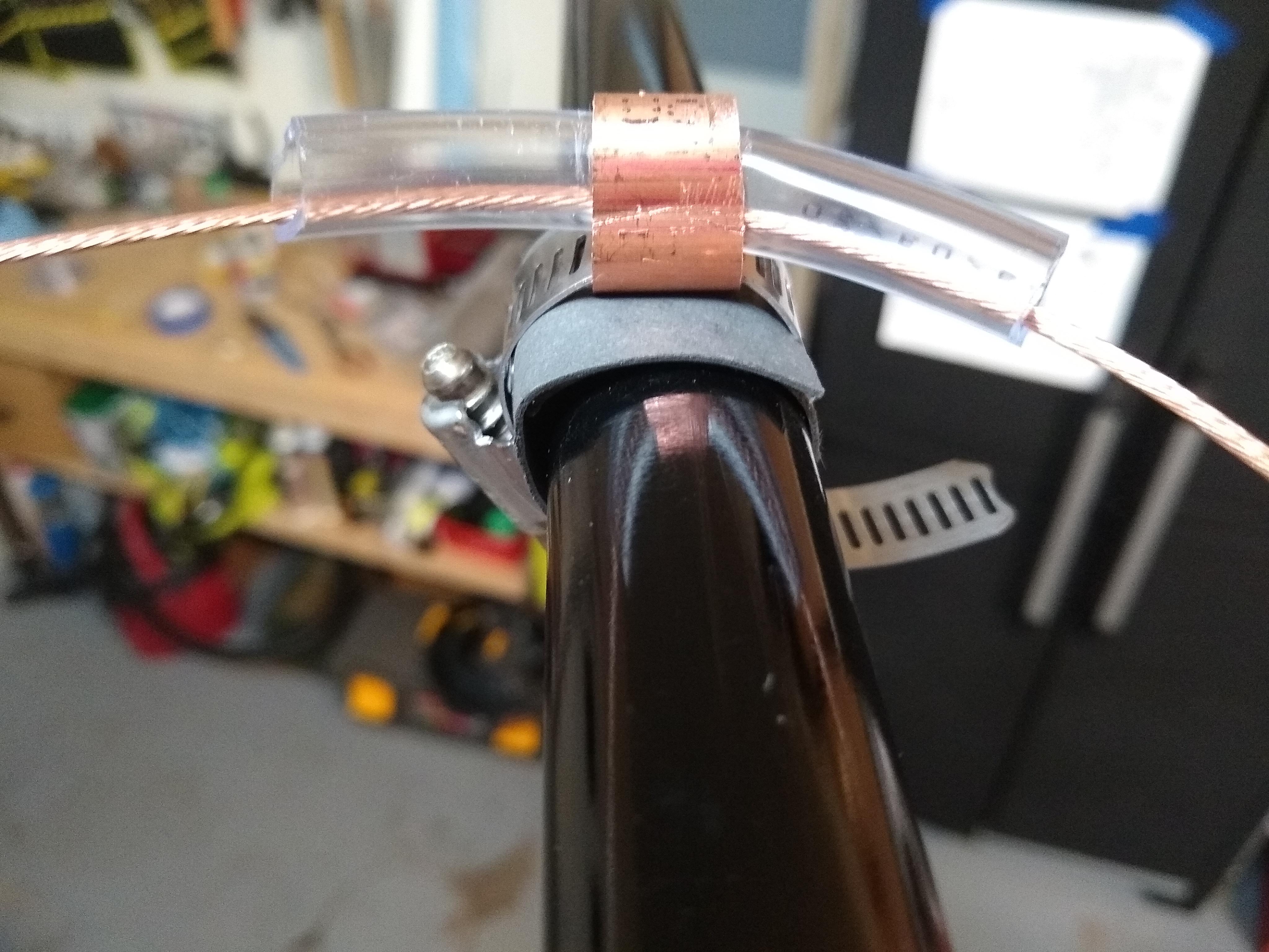
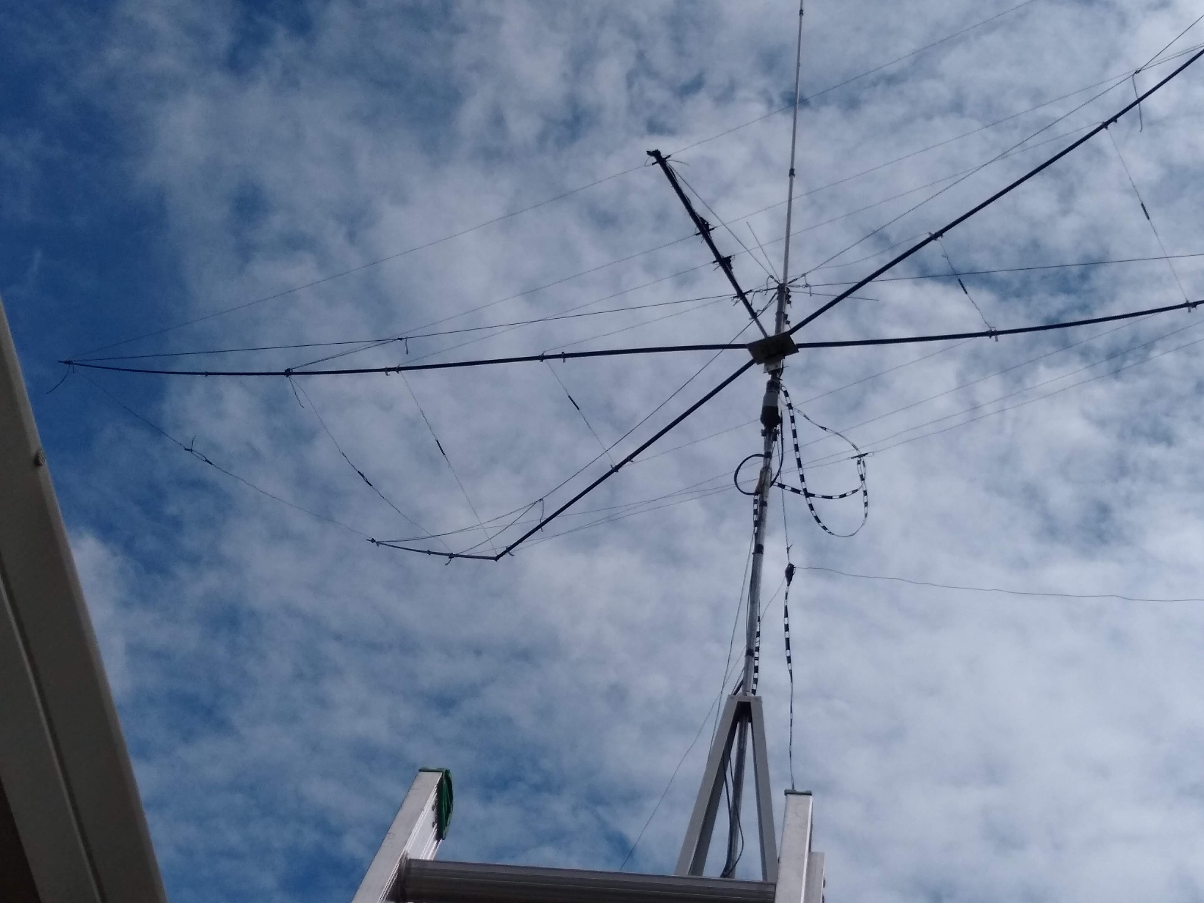
Fig. 11 - Clamps for running the wire. Take care not to overtighten, or broken spreaders result, as I am keen to know!
To keep the spreaders from collapsing back in I used hose clamps, on the outside of the friction joint. Putting too much pressure on the joint itself resulted in failure! I had to replace a broken spreader because of overtightening (see Figure 11). Appropriate use of electrical tape or some other wrapped material can spread the clamp pressure evenly around the fiberglass tube.
Ropes were secured to the top of the short mast section in order to support the fiberglass spreaders and provide more strength to the structure. I also didn't like the appearance of the spreaders drooping down and didn't want all the tension on the antenna wires. Turnbuckles were used to adjust the ropes to their final tension.
For the 50 ohm balanced feedline between the elements, I ganged RG-8X coax as per the referenced sites [1] and [2]. Mine are shown in Figure 12.
The feedpoint balun consists of 10 clip-on ferrite chokes slid into the feedpoint boom. The feedpoint boom itself is made from the largest diameter section
of one of the crappie poles, slide over a piece of PVC pipe that is u-bolted to the hub.
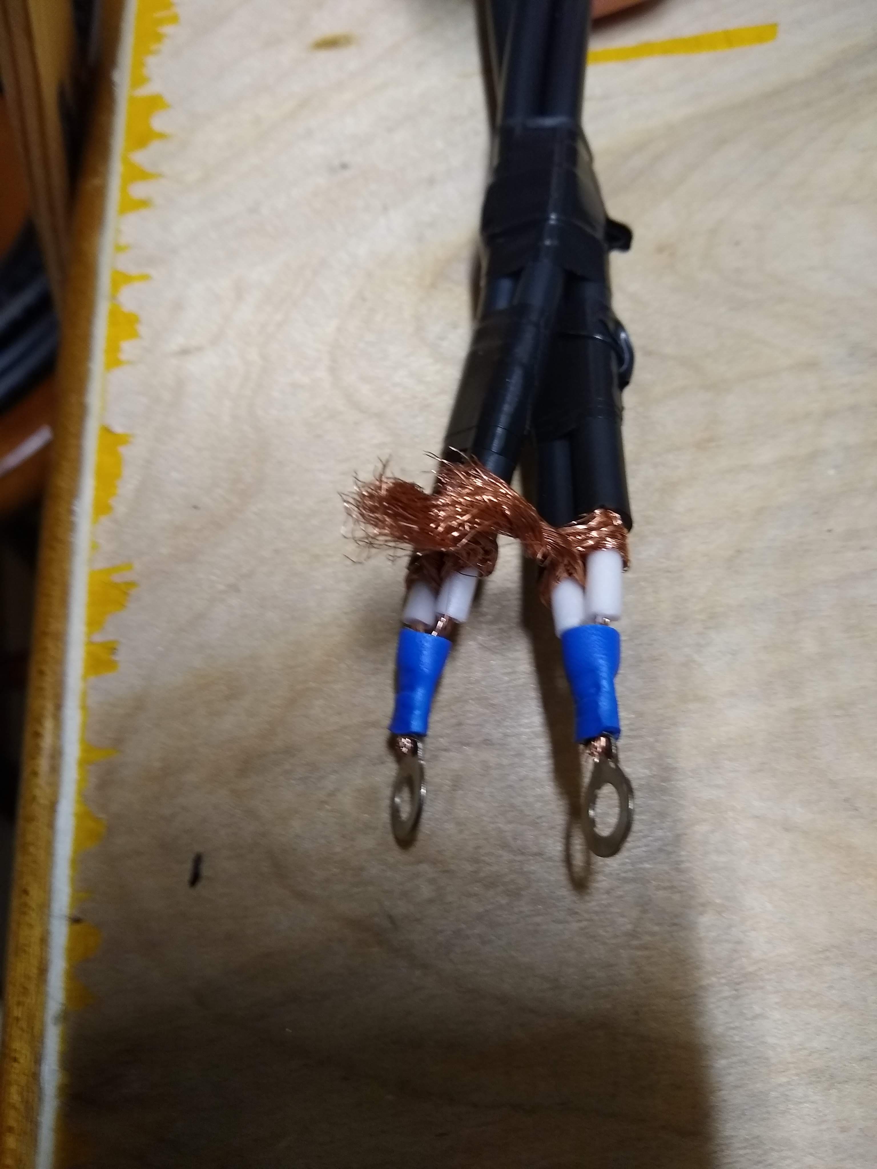
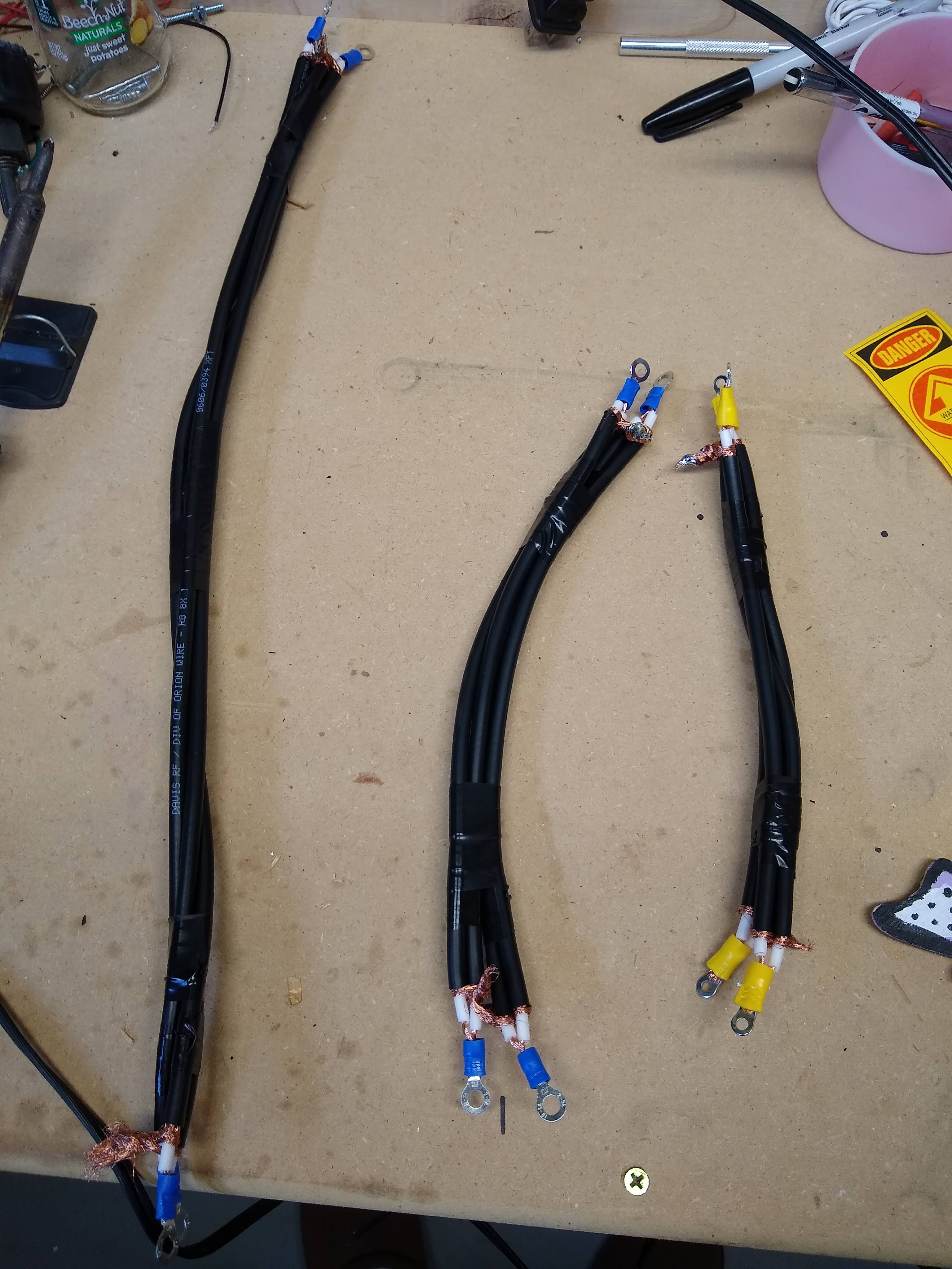
Fig. 12 - Balanced 50 ohm feeders.
The antenna elements are made from inexpensive THTN wire, which I stripped using a box cutter to "unzip" the insulation from the wire. This technique proved to be very fast
once I got the hang of it. I chose to remove the insulation in order to not have to correct for the velocity factor of the insulation.
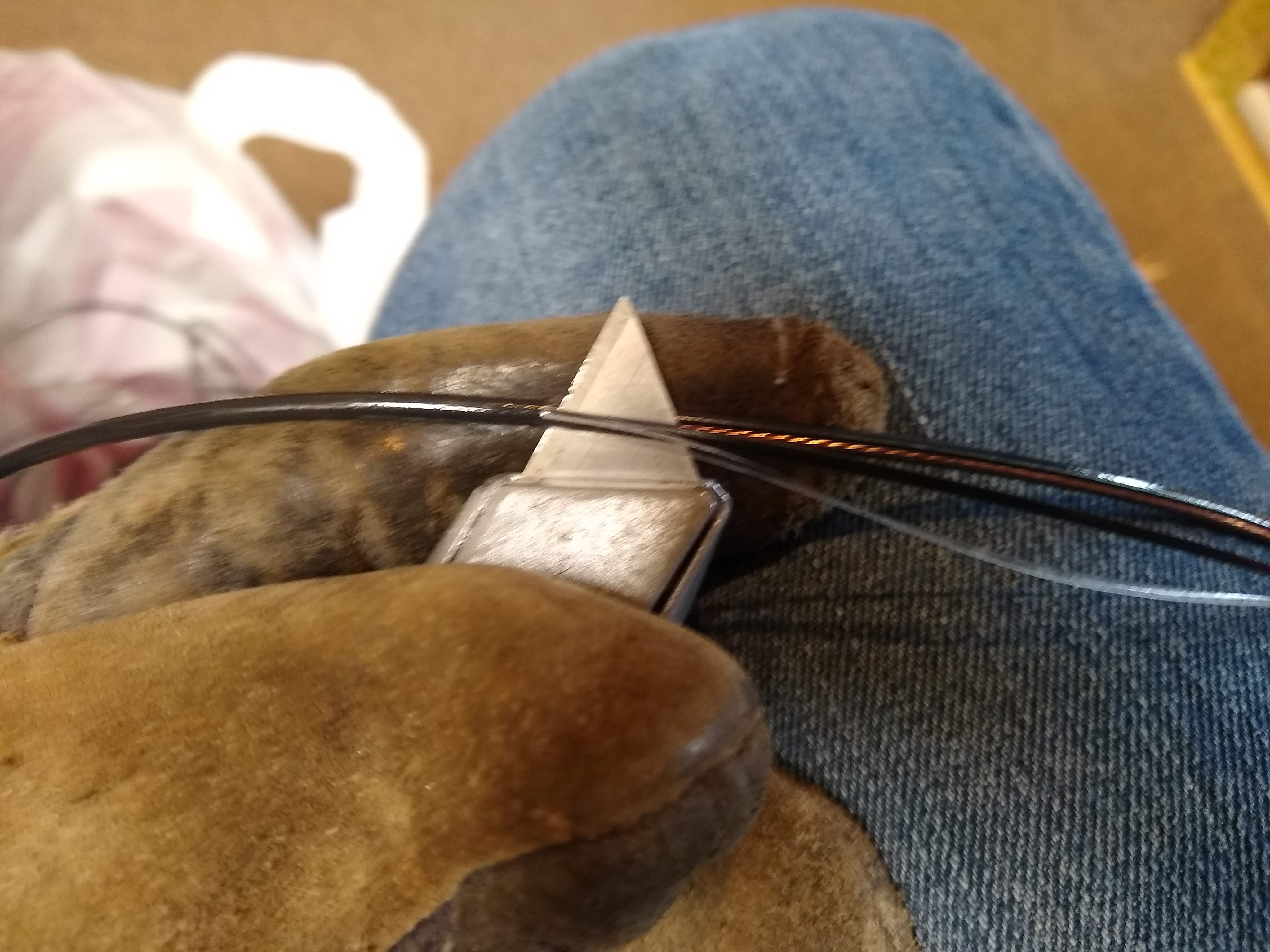
Fig. 13 - Wire strapping technique.
I was able to assemble the 6m, 10m, and 15m elements in my garage, but 20m would have to wait until Raising Day. It was simply too large to fit inside!
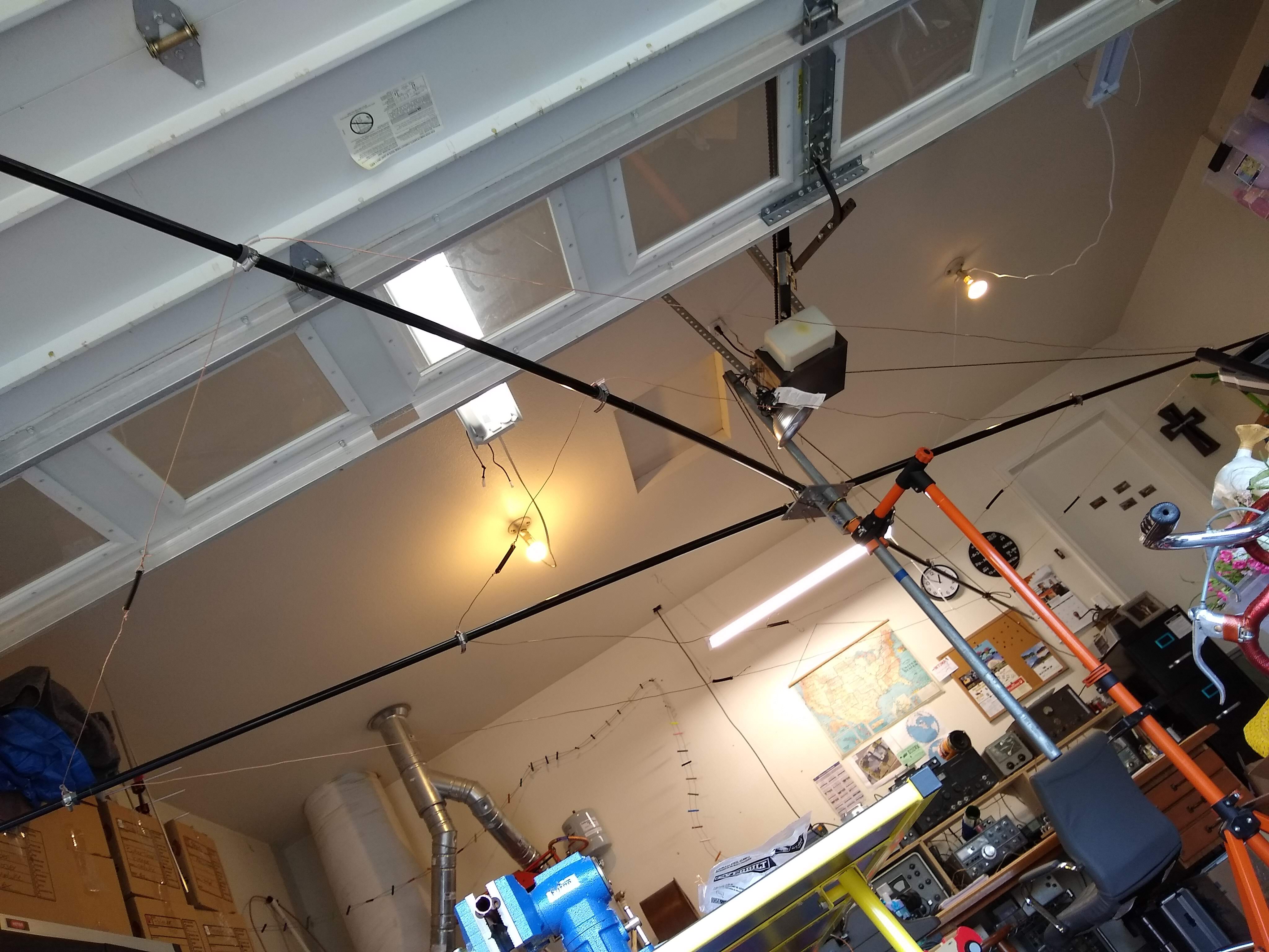
Fig. 14 - Assembly in the garage.
Moxon Raising Day
On a clear Sunday morning in April, it was time to raise the Moxon up to the rooftop tower. Many thanks to my friend John for his assistance! I had to wait to assemble the 20 meter element until the morning of raising, since as I mentioned it's too large to fit in my garage. I had eagerly been building up to this day for many weeks.
I had carefully worked out a plan for:
- Assembling the beam on the driveway
- Tilting down the tower
- Moving the already present doublet and 2m/70cm vertical out of the way
- Installing the rotator
- Raising the beam to the roof
- Attaching and final assembly of the beam
- Reattaching the VHF/UHF vertical
- Tilting the tower back up
- Functional testing
- Snagging some DX!
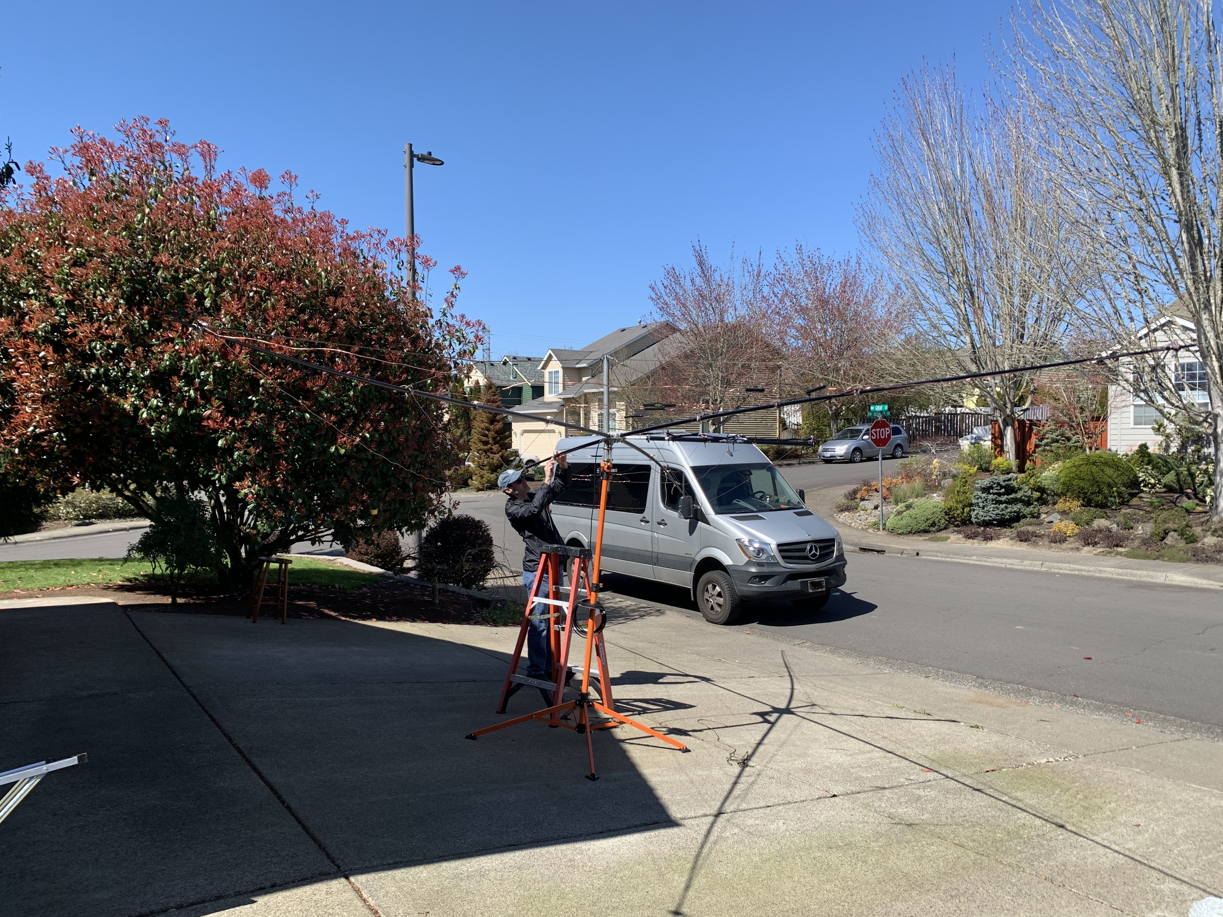
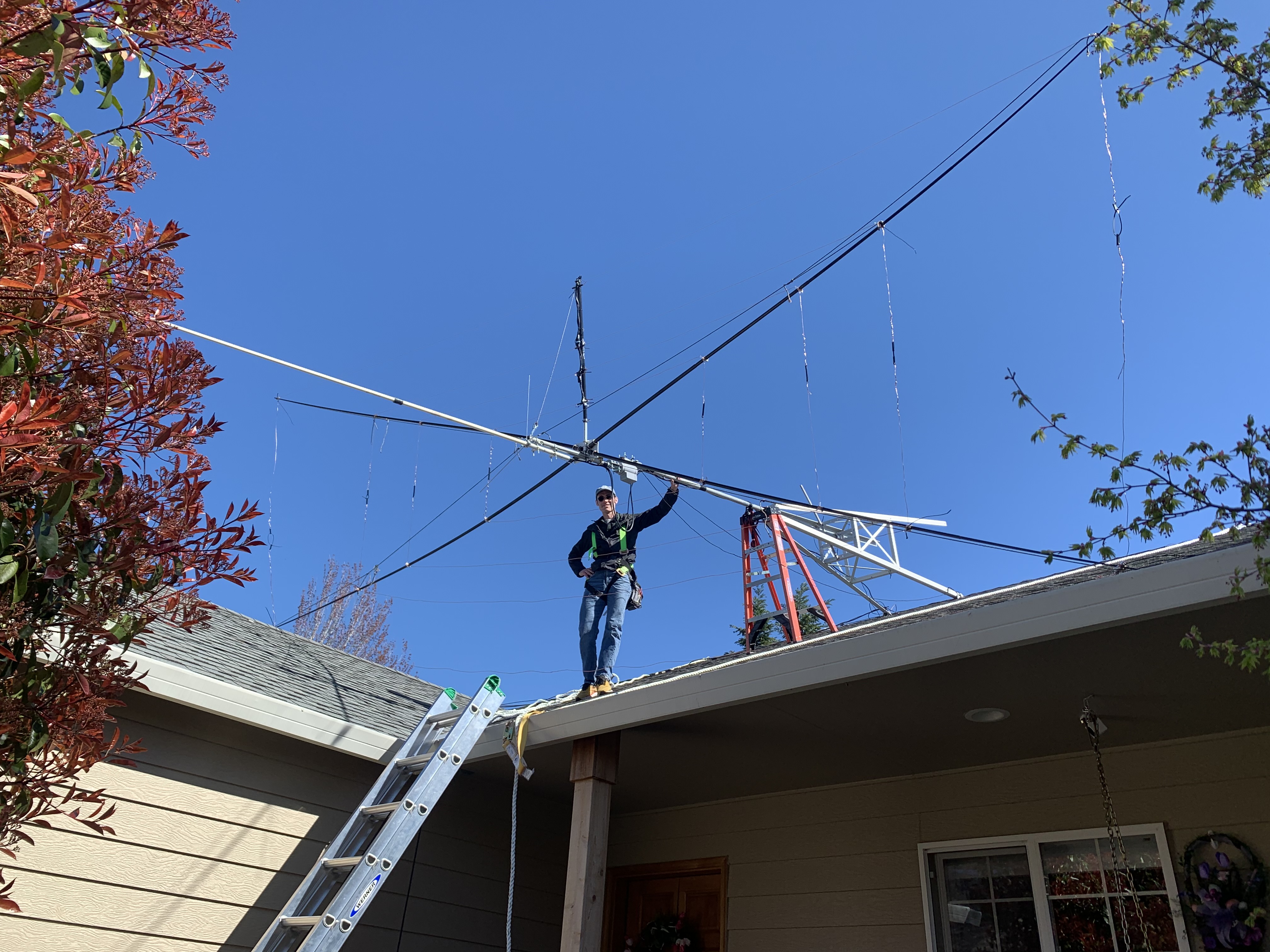
Fig. 15 - Assembly on the driveway and on the roof prior to tilting up.
Thankfully the beam fit well enough on my roof, anything larger would have been inconvenient to raise up to the roof or secure to the
tilted down rooftop tower. We took care to wear safety harnesses! Well worth the investment. Safety first!
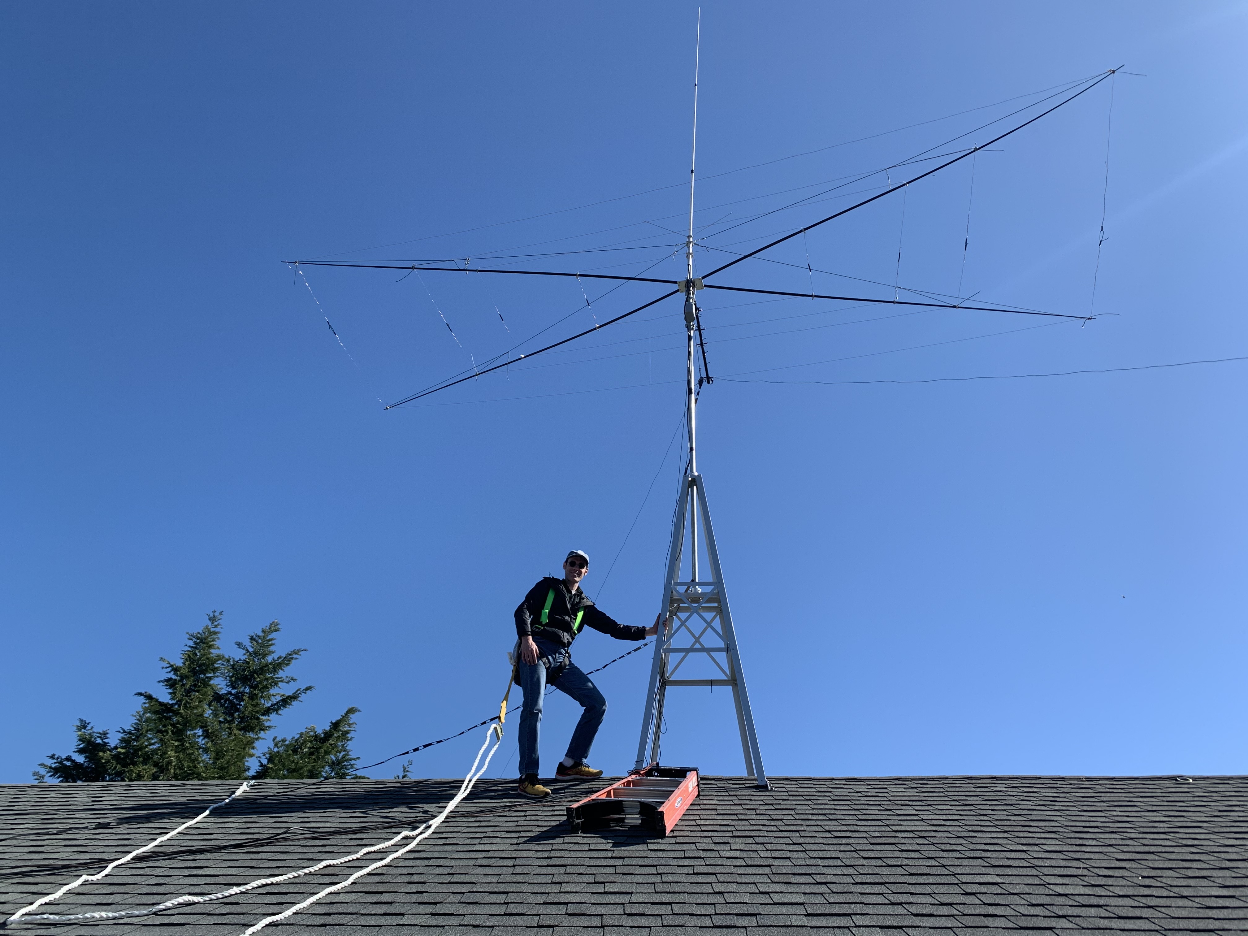
Fig. 16 - Completed beam prior to testing.
I couldn't believe it, I had a beam up in the air! Time to use it! We spent most of the day on the work, but thankfully my plan worked out well.
Initial testing
That we measured the pattern using S-meter readings, shown in Fig 17., and sadly it was clearly just a dipole pattern! I did not put a lot of effort into trimming it to the exact critical lengths! Although it wasn't what I wanted, I was not discouraged and knew it was time to tune it up.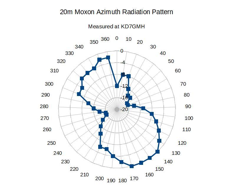
Fig. 17 - Initial 20 meter pattern measurement.
Researching options for Tuning
After some thought I ended conceiving an idea like in Figure 18. My desire was to be able to climb the roof and adjust the beam without having to tilt it down, and so I figured since a half-wave tuning stub "repeats" the impedance seen at one end to the other, I should be able to put a loading coil (or capacitor, if needed) on its end.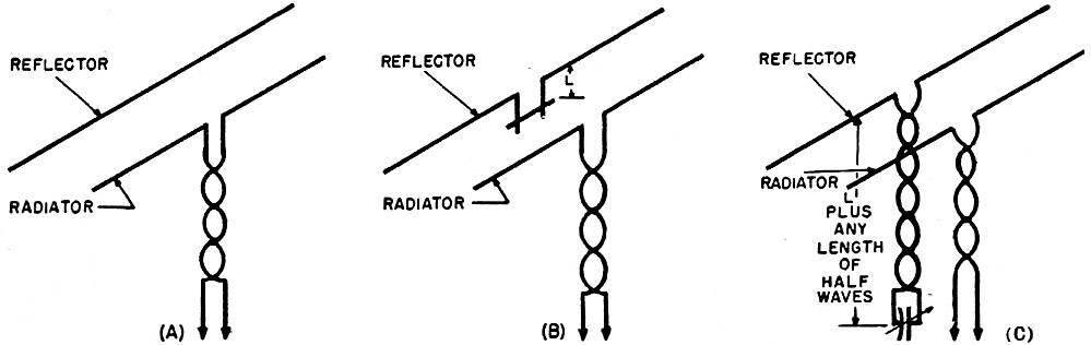
Fig. 18 - Half-wave tuning stub to permit in-situ adjustment of the reflector element.
Some extensive searching after I had the idea revealed that at least one other published author had done this before.
[5] http://www.rfcafe.com/references/radio-news/beam-antennas-radio-television-news-february-1950.htm
Re-tuning Strategy
I decided to connect a half wave balanced line to the 20 meter reflector and adjust a loading impedance, very likely a coil, for optimal gain or F/B.I ended up choosing a coil because a tuning stub would have been around 6 feet long, refer back to Figure 8 for the schematic. Some quick calculations for 20 meter center loaded dipole to resonate at 5% below the band (13.4 MHz) would require a loading inductance of about 0.6 microhenries. I already had an air wound solid copper wire coil of about that value. To cut the balanced feedline to λ/2 I used my trusty Heathkit grip dip meter.
To optimize the adjustment, I would use on-air testing to set the coil, described later.
Initial Tuning Results
I was able to add the loading coil to improve my reflector, connecting it through the 1/2 wave line.
I just adjusted it until it dipped at 5% below 14.100MHz (so 13.4 MHz). Without the coil the reflector was resonating around 14.4 MHz. (shame on my imprecise work!)
Later I came back and adjusted using over-the-air testing.
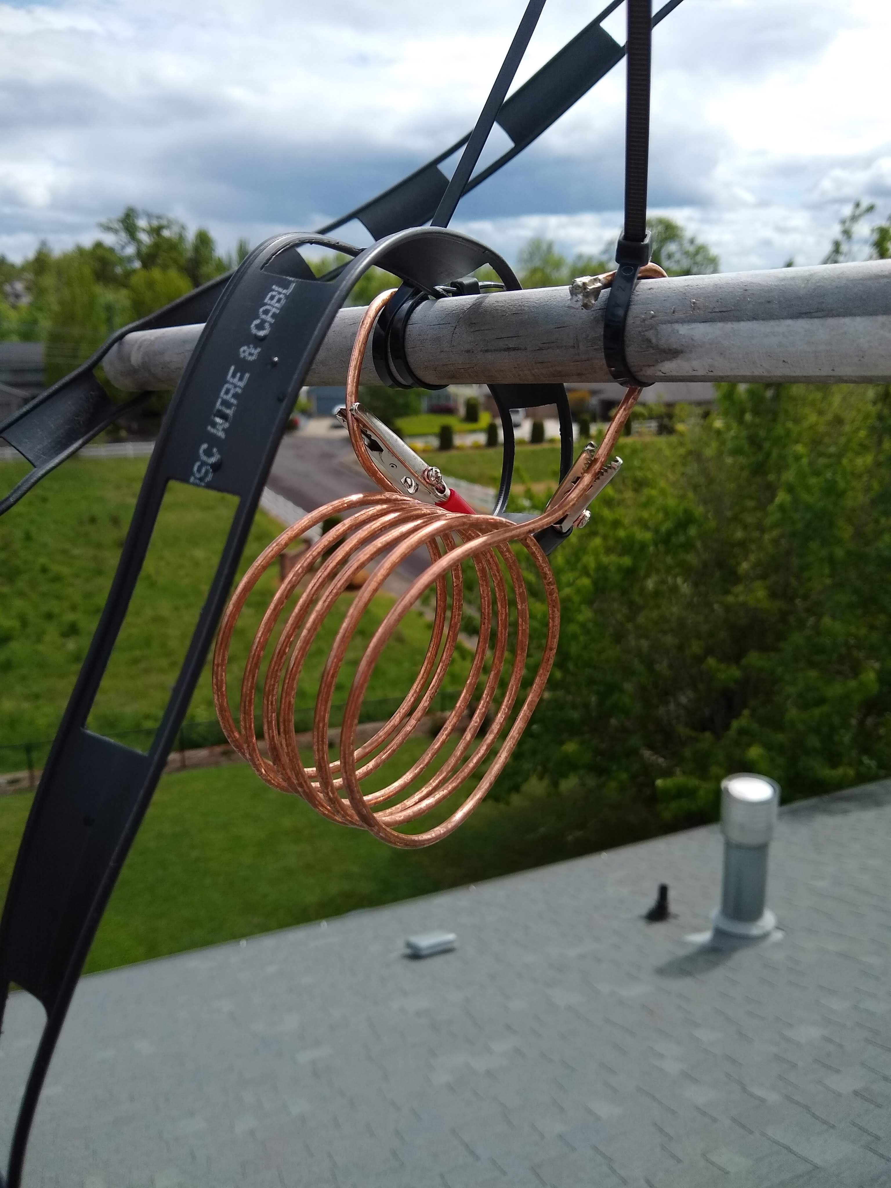
Fig. 19 - Loading coil at the end of the 20m half-wave stub used to adjust the 20m reflector.
I worked France the same afternoon I adjusted it, and for the first time the CW Reverse Beacons are reporting me in the EU. I'll probably get someone local to measure my azimuthal pattern soon, but my guesstimate is 2 S units front to back. Back is definitely weaker than the front.

Fig. 20 - Reverse beacon results. Results! I had not been spotted in EU prior to this.
Optimized F/B ratio
I had a couple ideas for enable over-the-air testing. What I really needed is a way to get an S-meter measurement on the rooftop as I set the loading coil, either by bringing a portable radio up there, getting someone to relay readings from down in the shack, or something else. I figured out that I could remotely tune with my laptop webcam aimed on the S-meter while on a video call to my smartphone. Technology at work!
One afternoon I pointed the back of the beam towards W1AW during their code practice QST and viewed the S-meter over the smartphone (Figure 21.) As I
set the taps on the coil I could dip the S-meter reading for maximal F/B ratio.
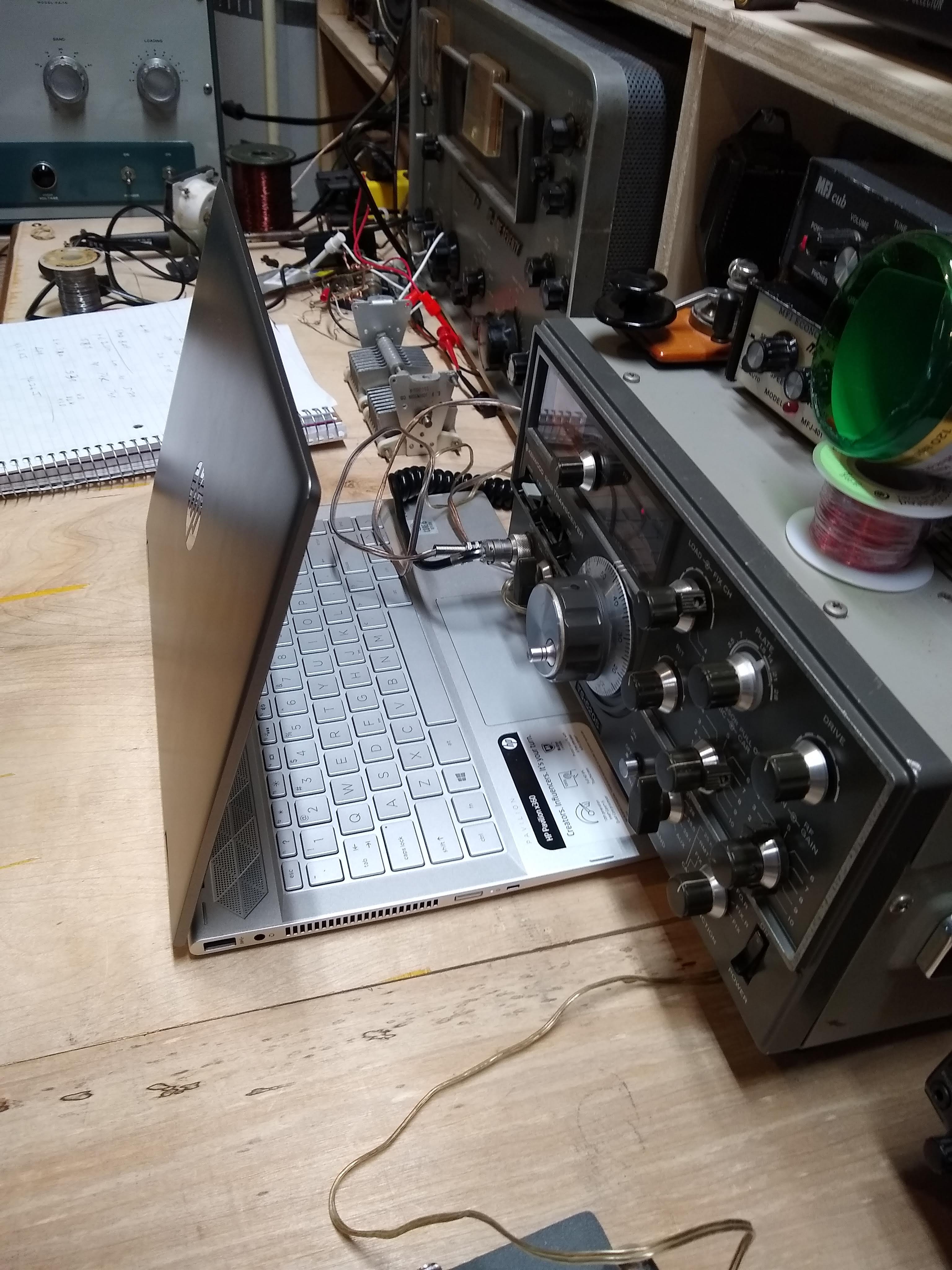
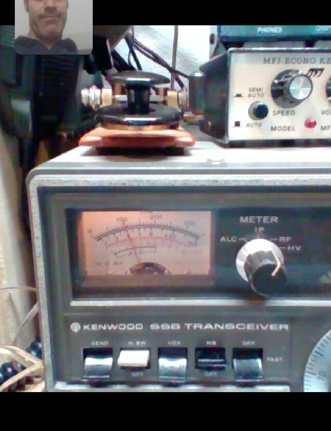
Fig. 21 - In-situ optimization of F/B ratio using a video call to myself.
After this adjustment, a number of quick tests indicates a front-to-back ratio of around 4 S-units! (though QSB made it difficult to precisely say). I'll have to enlist the help of a friend to record the pattern again. In one case, I had called CQ and a Hawaiian station returned the call while it was pointed about 180° away. They went from S4 to over S7.
Conclusions
Since erecting the beam I have been able to make regular contact to EU, with received single strength a couple S units better than the antennas I had
been using previously. I was also able to use it make a number of sporadic E contacts on 10m as well as my first couple of sporadic E contacts on 6m! I
have received consistently good reports about my signal strength on 10m and am very happy with the results of the project so far. This is the best HF
antenna I have ever owned and look forward to many great QSO's with it.
Created 15 April 2021
Edited 2 July 2021
Copyright James Palmer.
end of line.