My Radio "PIXIE2"

One day, it was just a incident but, I found a very inexpensive radio kit at
HSC, a store selling wide range of electrical components located at the heart of Silicon valley. It is called "PIXIE2" and sold with a price tag of $9.99!It was a back order item because of the high demands from many QRP enthusiasts in the valley; however, I got it after the several iterations.
This radio consists of just two transistors and one IC along with just minimal components, but it offers bare born functions of two-way radio.
The impressive thing is neither RF coil nor RX/TX switch is used. It is quite unusual for a radio design.

Local oscillation circuit is a standard Collpits B-E circuit. Emitter output has enough driving ability so that no frequency drift was observed during a transmitter operation where a load gets heavier.
A key point is that it uses just one transistor for both a transmission and a receiving operation. I forgot to draw a key connection in my schematic but, the key should be connected between emitter and ground of the final transistor. The collector is always connected to an antenna regardless of the mode of operations. The same thing is for the base connection with a local oscillator. Therefore, only bias condition of emitter determines the operation.
While receiving mode, it is biased as class C and works as current mode switch as a product detector. The estimated conversion gain is 0 dB since it is a reverse mode of transfer function of the transistor.
The detected audio signal then is amplified by LM386. This produces a sound large enough to drive a small speaker for use in the room. I usually use Walkman type headphones and works really well. The total gain of this receiver is just 42 dB solely generated by audio stage.
It will change to transmitter mode when key is pressed. The final transistor will work as emitter grounded amplifier. My radio uses 2N3904 (a generic transistor similar to 2SC1815 in Japan) and actual measured output power (by a spectrum analyzer) is 13dBm (20mW).
As everybody does, I modified it to be personalized. Here are my MODs.
First I added a side tone circuit. I taught I could make it simply by adding a positive feed back to the input of LM386. However, PIXIE2 uses an inverting input so this is not applicable.
As an alternative, I made an oscillator using a 4011 from my junk box. It does not take a lot of current. Besides, one gate buffer can drive headset nicely (better than what I thought). Entire circuit can be build with 10mm X 10mm X 3mm thanks to SOP package. So, I put it under a key connector. The circuit can be seen at Fig below.
3V Zener diode limits voltage swing by 3V as well as current consumption.

Not too many PIXIE2 uses VXO with reasonable coverage. I used Super VXO method where two crystals are used to obtain wider coverage. After the optimization (experimenting with over 40 different coils), I discovered 41 Turns with 10K core (that can be found in old radio and Televisions) were a optimal condition. With the constants shown below, I could tune from 7027 to 7043 without having an unstable condition. I use one dedicated trimmer for a RIT function. It provides comfortable tuning and perfect Zero-in to your counterpart.
Additional feature of my version is enabling multi-band operations by replacing a tuning block. I prepared 40m module and 30m module already.
First of all, This RIG with 3m-wire antenna does not work. As I mentioned, this RIG has only 42dB gain compared to a typical 90dB gain, which most others have.
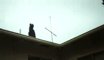
So, I went to Orchard Supply (!) and grabbed coax cable and steal wire to build an inverted V antenna while my wife went for a shopping. It was set up at about 15ft high within an hour or so.
A picture below is how it looks like. It seems like working well since it is a full-size. I could not use a full size antenna in Japan because the land is limited and it is a premium (expensive).

PIXIE2 and the new antenna worked really well not only for ham signals but also AM810! So, I have to reduce the broadcasting signal down. By couple of experiments, one way to eliminate it is to insert a coupling C (1000PF) between an antenna terminal and PIXIE2. This represents 20% of power loss at 7MHz; however, I decided to do so since whole purpose of this radio is for QRPp operation anyhow.
Problem solved!
After all, my radio works very well. I listened VK, JA, XE, VE and of cause many W's.
The total cost of my station is less than $100. Is that sounding good to you? So now it's a time to operate it.
Return to Home Copyright 1997 JJ1SLW --- This is a link free page---