Power Supply
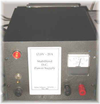
20A
(and more) - 13,8V
Power Supply
Clic here for electric schematic
An other
one ???? ...... Yes.
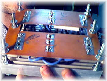
The starting problem was to recycle some things: chassis, transfomer, heat sinks
etc: what to do?
A power supply, of course !
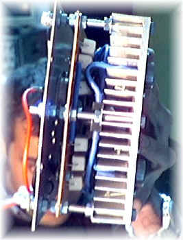
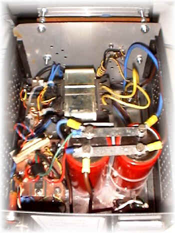
This time I've stabilized the negative side using 6 cheap 2N3055 with collector
directly mounted on the chassis.
TRANSFORMER
My
transformer was 220/19V;
you can calculate the power it can give by the core dimension, but I've
preferred use a practical way:
I've used a 100 meter / 1,5 mm wire and measured its resistance; it was about
1,1 ohm; so I've connected it to the output of the transformer; after about 30
seconds the transformer was still cold; well, due to the Ohm's law, the
trasformer was able to supply at least 19 / 1,1 = 15-18 ampere: OK, it was
good.
RECTIFIER BRIDGE
Rectifier bridge's
diode usually see a voltage of Vout x 2,828, so it's better
to use one with a PIV 3 or 4 time bigger than the output voltage
(19x3=57V);
same words for the current: a 50Ampere bridge has been used.
At first I've used a 25A one and infact after few test it has broken.
CAPACITOR FILTER
For a bridge rectifier you must use the following formula to calcule the amount of needed capacitance:
C= 1,8 x (I / VR)
where I
is the max current and VR is the max ripple;
if a stabilizer follows the capacitors (as here), then you can use a value 40%
lower than the calculated one; in my power supply I've used 2x 22000 microF / 40VL.
The working voltage of capacitor should be at least 40 % bigger than the output
voltage.
STABILIZER IC
I've
used a LM7912.
The basic schematic is in the following picture;
U1 give
only a part of the output current (the value is limited by R1); under this
value Q1 is "closed" and only U1 supply the load; if the load need
more current, then voltage drop across R1 (more than 0,7V) cause Q1 to
open giving the remaining current;
practically Q1 is composed by a paralell of some transistor.
R2,R3 and V1 let you vary the output voltage; D1 is used to avoid that
reverse currents came back into U1.
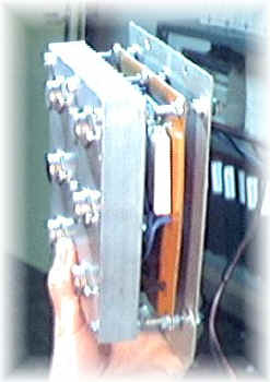
TRANSISTORS
The
needed output current is 20 Ampere;
The input voltage for U1 is
(19 x 1,414)-1,4 = 25,4 unloaded
25.4v x 0,9 = 23v loaded
in the case of a output voltage of 13,8V (for a typical RTX) at 20 Ampere, transistors need to dissipate 180W, but usually it's better to consider a value 3 time higher (500w);
A similar transistor does not exist (in my shack), but there're many 2N3055 with
the following charateristic:
100V max
voltage;
15 Ampere max collector current;
115W max dissipation power;
So I've used a parallel of 6 x 2N3055 obtaining about 700w.
On each collector a 0,05/0,01 ohm resistor is needed (to equalize currents);
I've added also an other 2N3055 (or any other NPN) to drive the other 6 one.
Use appropriate wire diameter
diameter=0,7 * SQRT ( I )
so, for
a 20 Ampere load, you must use a wire with a diameter of 3mm (AWG 9).
Take wire as short as possible to avoid voltage drop under maximum load.
In many power supply the negative is insulated from chassis: that's nice but
when the load is a radio-tranceiver, usually the negative is shorted with its
chassis (common also to the ground of antennas, house etc.);
so, to avoid ground loops, I've connected the negative to the chassis.
PROTEZIONI
Simpler and more stupid protecions are always the best:
-a bipolar switch,
-a input pi-greek filter,
- a fuse (2A on 220V side, 30A on the 13,8 side
- some by-pass capacito on the output and some VK200 on the stabilizer IC;
There is also a short cut protection, wich use a rele' (usually on), switched
off when short cut occurs.
METER
I've used the first meter I've found adding a serie resistor and remaking the scale with a dedicated software (by wb6bld).
NOTE
-I've noted U1 to oscillate; the problem was solved simply removing any
capacitor at the output.
- to make U1 working correctly, I've used a second transformer to supply the
protection cricuit.
Clic here for electric schematic
73 de iz7ath, Talino Tribuzio