DUMMY LOAD FOR HF BAND
This is a easy dummy
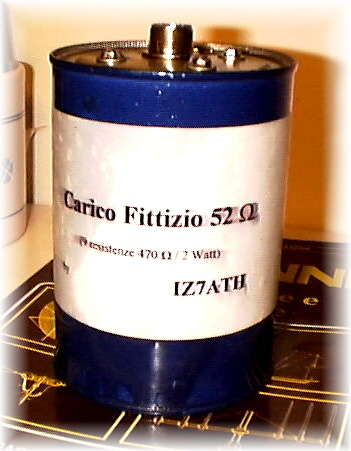
load; I used common 2W/470 ohm resistor in parallel, obtaining 52 ohm/18 watt;
you must know that if you want a precise dummy load for high frequency you need a
no-inductive resistor (those in the picture have high precision until VHF, I never tried
up, see Picture 1), because the common
resistor, going up with frequency, have more and more high inductive value;
but you can useful use the common resistors if:
I'll explain better with an example: I put my
"precise" dummy load (with no-inductive resistor) back my RTX and have measure
S.W.R.; it was 1:1,1 from 1.8 MHZ to 144; I removed it and have used this new one: I have
S.W.R. 1:1,1 at 1,8 MHZ and 1:1,2 at 28 MHZ, but at 144 MHz IT'S 1:2.
In HF band you can use it (a S.W.R. 1:1,2 is OK) for all uses (testing coaxial cables,
tune antennas, linear amplifier ecc.); but you can not use it on VHF.
Common resistor have an inductive value when you go up with frequency; but we also know that:
From 1) cames that we can use common resitor
making a parallel; so doing we obtain an higher power dissipation; in my one I have
obtained 18 watt: putting the resistors in a liquid (oil in my one) we make this value
higher; in my dummy load I usually put 100 watt for medium-short time with no problem.
About oil to use I think the transformer one is the best (I put used oil caming from my
moto HI).
From 2) cames that we can use common resistor on high frequency adding a capacitance: if we put around a common resistor a small copper sheet, a metallic sheet (the dummy load box) or two metallic plate ecc. we obtain a capacitor that let we use this dummy load on the high frequency (be careful; dont' exceed with capacitance).
Let's see now how I build
it: as box I used a metallic one used for containing paint (see pictire 2); put the SO239 (with the dummy load
soldered) on the top (on a metallic plate) and then put the box and the plate together
using 4 screw bolt (3mm)(see picture 3).
I pour the oil in the box trough a small hole (closed with an screw bolt) (make sure the
oil cover all the resistors).
The resistors are soldered on two copper plate (the same you use for printed board) trough
9(x2) holes: in this way you have a small capacitor to make the inductance value lower.
You can build also dummy load for 75 ohm or
other values for various tests.
These are the Resistive (R) and Reactive (X) value measured with my MFJ259B in the range 0-170MHZ relative to my home-made dummy load
| Freq. | R (ohm) | X (ohm) |
| 0 (DC) | 51 | - |
| 1 | 51 | 0 |
| 2 | 51 | 0 |
| 3 | 51 | 0 |
| 4 | 51 | 0 |
| 5 | 51 | 0 |
| 6 | 51 | 0 |
| 7 | 51 | 0 |
| 8 | 51 | 0 |
| 9 | 51 | 0 |
| 10 | 51 | 0 |
| 11 | 51 | 0 |
| 12 | 51 | 1 |
| 13 | 51 | 1 |
| 14 | 51 | 2 |
| 15 | 51 | 2 |
| 16 | 51 | 2 |
| 17 | 51 | 3 |
| 18 | 51 | 3 |
| 19 | 51 | 3 |
| 20 | 51 | 3 |
| 21 | 51 | 4 |
| 22 | 52 | 4 |
| 23 | 52 | 5 |
| 24 | 52 | 5 |
| 25 | 52 | 5 |
| 26 | 52 | 5 |
| 27 | 52 | 6 |
| 28 | 52 | 6 |
| 29 | 52 | 7 |
| 30 | 53 | 7 |
| 35 | 54 | 7 |
| 40 | 55 | 9 |
| 45 | 55 | 9 |
| 50 | 60 | 8 |
| 55 | 61 | 10 |
| 60 | 63 | 10 |
| 65 | 65 | 10 |
| 70 | 66 | 7 |
| 75 | 68 | 13 |
| 80 | 71 | 14 |
| 85 | 74 | 13 |
| 90 | 79 | 10 |
| 95 | 81 | 10 |
| 100 | 88 | 0 |
| 110 | 95 | 0 |
| 120 | 97 | 0 |
| 130 | 101 | 6 |
| 140 | 101 | 30 |
| 150 | 96 | 35 |
| 160 | 95 | 40 |
| 170 | 97 | 40 |
The following are value of my 1Kw dummy load using a single 300W anti-inductive resistor (by MFJ)
| Freq. | R (ohm) | X (ohm) |
| 0 (DC) | 59 | - |
| 1 | 59 | 0 |
| 2 | 59 | 0 |
| 3 | 59 | 0 |
| 4 | 59 | 0 |
| 5 | 59 | 0 |
| 6 | 59 | 0 |
| 7 | 59 | 0 |
| 8 | 59 | 0 |
| 9 | 59 | 0 |
| 10 | 59 | 0 |
| 11 | 59 | 0 |
| 12 | 59 | 0 |
| 13 | 59 | 0 |
| 14 | 59 | 0 |
| 15 | 59 | 0 |
| 16 | 59 | 0 |
| 17 | 59 | 0 |
| 18 | 59 | 0 |
| 19 | 59 | 0 |
| 20 | 59 | 0 |
| 21 | 59 | 0 |
| 22 | 59 | 0 |
| 23 | 59 | 0 |
| 24 | 59 | 0 |
| 25 | 60 | 0 |
| 26 | 60 | 0 |
| 27 | 60 | 0 |
| 28 | 60 | 0 |
| 29 | 60 | 0 |
| 30 | 60 | 0 |
| 35 | 61 | 0 |
| 40 | 61 | 0 |
| 45 | 61 | 0 |
| 50 | 62 | 0 |
| 55 | 63 | 0 |
| 60 | 63 | 0 |
| 65 | 64 | 0 |
| 70 | 64 | 4 |
| 75 | 65 | 5 |
| 80 | 66 | 4 |
| 85 | 67 | 6 |
| 90 | 66 | 9 |
| 95 | 69 | 9 |
| 100 | 68 | 13 |
| 110 | 68 | 16 |
| 120 | 65 | 22 |
| 130 | 64 | 26 |
| 140 | 61 | 29 |
| 150 | 61 | 31 |
| 160 | 58 | 37 |
| 170 | 61 | 43 |
The following are value of a dummy load made with a single "wire power resistor"
| Freq. | R (ohm) | X (ohm) |
| 0 (DC) | 56 | - |
| 1 | 56 | 0 |
| 2 | 56 | 0 |
| 3 | 56 | 0 |
| 4 | 56 | 0 |
| 5 | 56 | 0 |
| 6 | 56 | 0 |
| 7 | 56 | 2 |
| 8 | 56 | 4 |
| 9 | 56 | 5 |
| 10 | 56 | 5 |
| 11 | 57 | 6 |
| 12 | 57 | 7 |
| 13 | 58 | 8 |
| 14 | 58 | 9 |
| 15 | 59 | 9 |
| 16 | 59 | 10 |
| 17 | 59 | 12 |
| 18 | 60 | 12 |
| 19 | 61 | 13 |
| 20 | 61 | 13 |
| 21 | 62 | 14 |
| 22 | 63 | 15 |
| 23 | 64 | 15 |
| 24 | 65 | 16 |
| 25 | 65 | 16 |
| 26 | 66 | 17 |
| 27 | 67 | 17 |
| 28 | 68 | 18 |
| 29 | 68 | 20 |
| 30 | 70 | 21 |
| 35 | 83 | 14 |
| 40 | 86 | 18 |
| 45 | 91 | 23 |
| 50 | 108 | 0 |
| 55 | 117 | 0 |
| 60 | 124 | 0 |
| 65 | 131 | 0 |
| 70 | 128 | 6 |
| 75 | 129 | 54 |
| 80 | 108 | 78 |
| 85 | 95 | 83 |
| 90 | 80 | 87 |
| 95 | 55 | 94 |
| 100 | 45 | 80 |
| 110 | 31 | 70 |
| 120 | 25 | 56 |
| 130 | 19 | 48 |
| 140 | 13 | 42 |
| 150 | 10 | 36 |
| 160 | 9 | 29 |
| 170 | 8 | 24 |
73 de iz7ath, Talino Tribuzio