- Transmitter: self-made, four tubes (schematics).
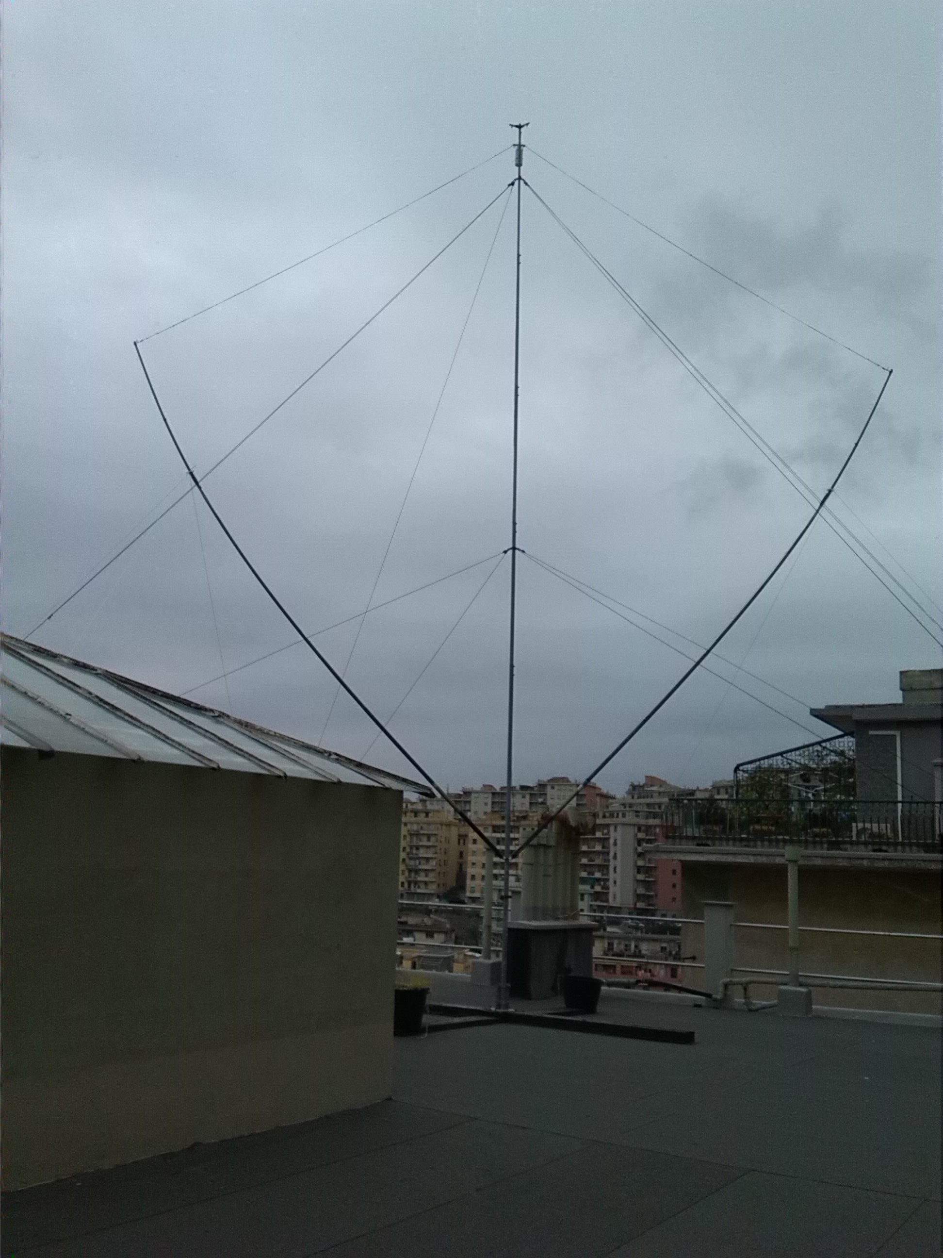
- Antenna: self-made inverted vee, 9.5 meters high (web page)
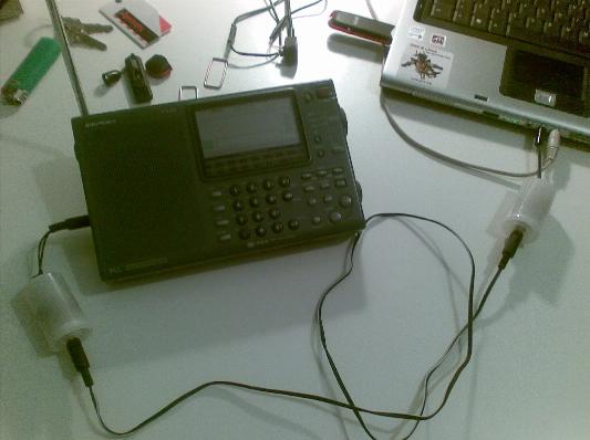
- Receiver: Sangean ATS-909 (picture)
|
|
Current status of my station:
|
|
|
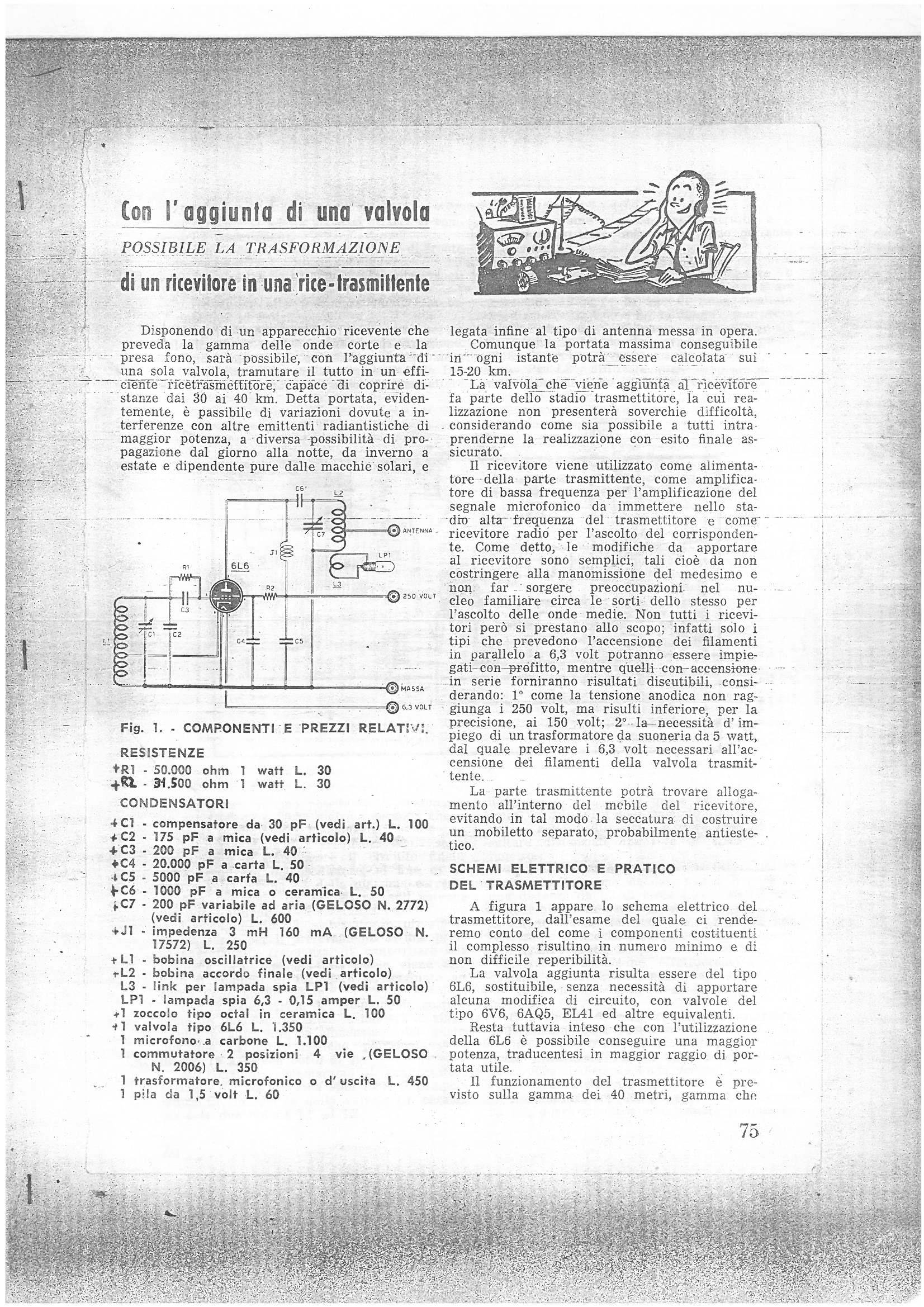
A copy from an old italian magazine of amatorial electronics,
proposing an add-on for tube receivers. The add-on was a simple
one-tube short-wave transmitter leveraging the same power supply
already available in the receiver. This circuit fascinated me
when I was just a teenager. Click on the pic for enlarging. |
|
I was quite a nerd when I was a teenager. Sure, besides being very clever at school, I was into any sort of strange hobbies including electronics. My father was seemingly proud of this. Perhaps my mother was a bit concerned, instead. You know, a male teenager is rather expected to hang out with friends, seek a girlfriend, etc..
The project reported in that old magazine fascinated me at that time, because I had a tube receiver at home, and I got a spare tube from another old receiver so I apparently had almost all the ingredients. The only missing piece was the plate RF choke, but I managed to build what at that time I presumed to be a good approximation of it. So I tried! But I was unsuccessful.
The reason of that early insuccess was a fundamental lack of specific knowledge in RF electronics. I had no actual chance to spread RF in the air, despite the schematics and the components, because for instance I knew nothing about antennas, transmission lines, and impedance matching. I will always be grateful to the poor victim of these early and cruel experiments, namely, a 6V6 tube that has survived nevertheless. Vacuum tubes are generous and patient, they tolerate our mistakes, and this is the main reason why I keep loving them for my RF experiments, despite the dangerously high voltages required for operation.
Then I went to the university and I had no more time for that hobby,
until recently.
|
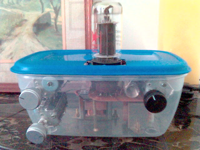
First serious attempt: one-tube tx using a Sovtek 6L6 WXT+ tetrode in a
Hartley electron-coupled oscillator.
Circuit schematics is missing, but it was very similar to
the one I attempted to build when I was a
teenager. As apparent in the picture, the rig was enclosed in a plastic
container originally intended for storing food into the fridge. Click on the pic for enlarging. |
|
The plate circuit of this rig requires a RF choke (see the approximate schematics) which is usually wound according to the famous "honeycomb" fashion to minimize stray capacitance. Since I was unable to find one in any shop, I had to roll my own one. It was fun to envisage a procedure for building it, and a nice bricolage when doing! You can look at the result in the next section.
Originally, both the grid and the plate networks were tuned in the 20 mt band; this way, however, the rig was almost impossible to tune. It looked like the plate network was oscillating on its own, taking over the grid resonant circuit (sort of "tuned-not-tuned" rig). This was perhaps caused by some coupling between the grid resonant network and the plate network, although the respective coils were mounted orthogonal to each other. As a remedy, the grid was then tuned in the 40 mt band while leaving the plate pi network on the 20 mt (frequency doubler).
Voltages were not regulated; plate voltage was 600 V, screen was about
250 V.
The rig offered some rudimentary AM (plate) modulation. CW was obtained by
keying the screen grid voltage.
Had no antenna nor license at that time; experiments with a in-house
dipole.
Had not even a real receiver initially; just a common transistor radio covering
part of the shortwaves.
Had no SWR meter, so tuning the dipole was kind of "magic"
(and very approximate).
Results, and problems:
No QSOs, due to lack of real antenna (and lack of license).
Chirp was really really bad when keying.
Overall a very simple rig, but unusable.
|
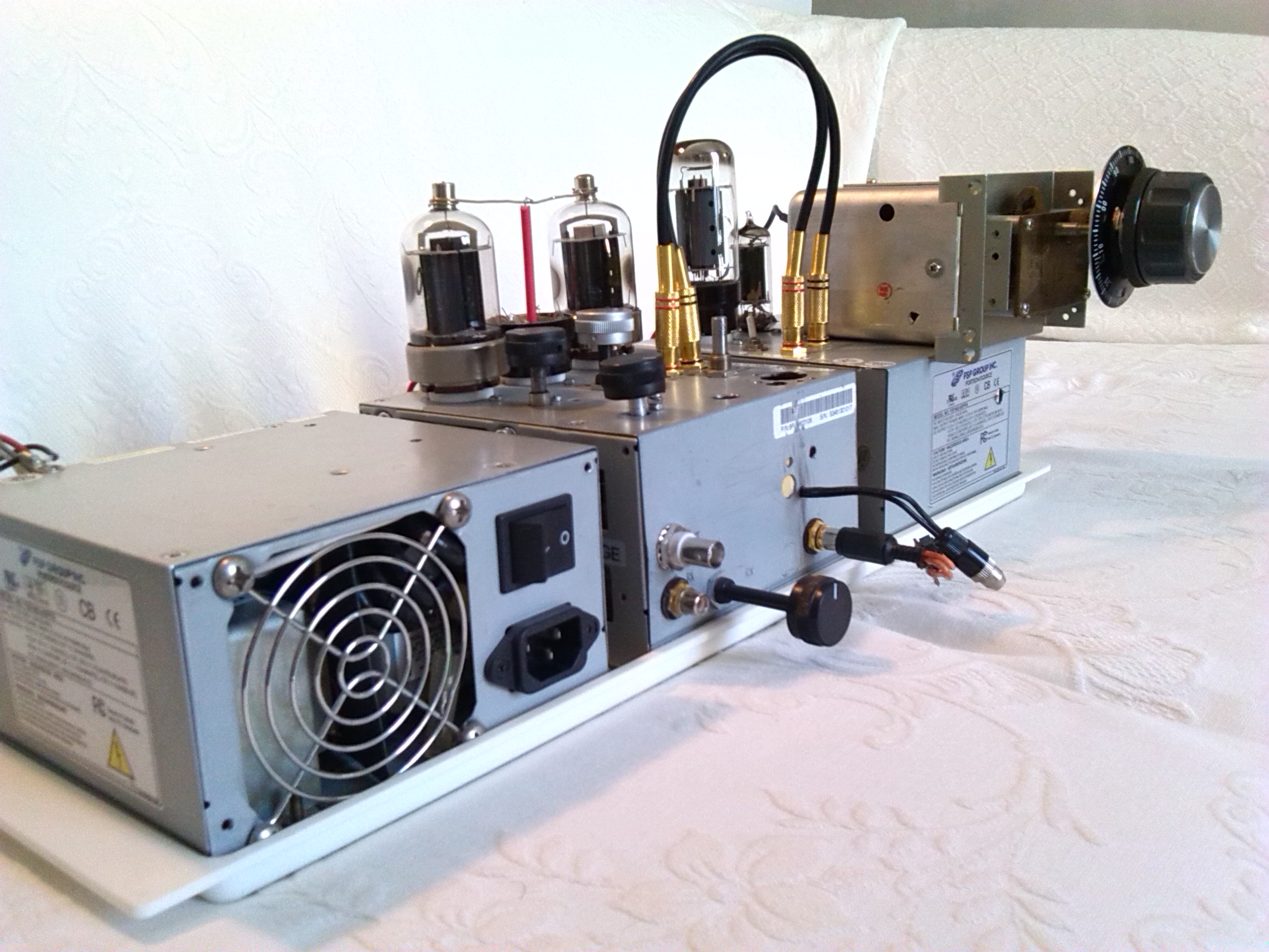
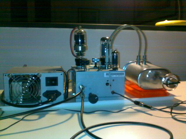
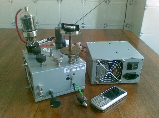
Two-tubes tx: 6V6 GT tetrode for the VFO, plus a 6146B class-C amplifier. The picture shows the two vacuum tubes (6146B on the left, 6V6 GT on the right), and the two separate enclosures (one for the rig and the other for the power supply unit); both are recycled from computer's broken power supply units. Click on the pic for enlarging. |
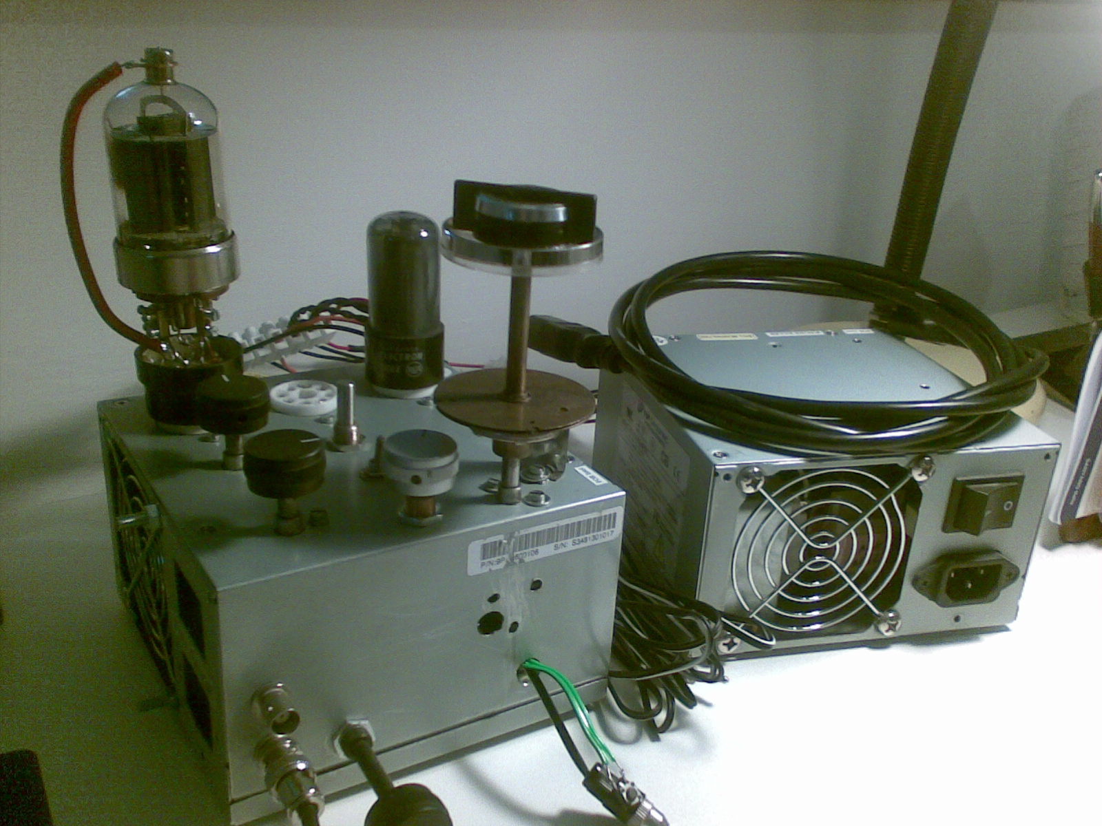
|
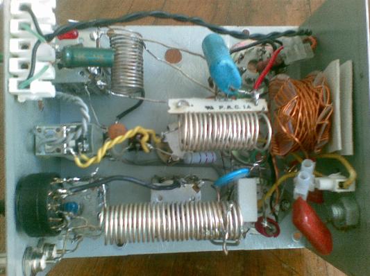
Another picture shows the unusually tiny size of this rig, in comparison to a mobile phone. A look at the interior shows the hand-wound honeycomb RF choke (enameled copper, hence the colour) already mentioned in the previous section. Finally, a picture of the final pi network shows the usual coil and the two variable capacitors.
Output RF power is in excess of 50 watt. In the early version of the rig, the VFO was a Hartley oscillator (see early schematics), later replaced by a Clapp oscillator; look at the schematics for details. Note that the plate and screen voltages are obtained by rectifying and doubling the mains, without any transformer. As a result, the chassis is at a dangerous -300 V with respect to ground. A galvanic connection to ground is thus impossible, unless a isolation trasformer is placed between the rig and the mains.
|
In this phase of my journey I had four precious companions, namely: a license (callname IZ1QZE), a SWR/power meter, a dummy load, and a clone of the Sangean ATS-909 (in the picture). This tiny but SSB-capable shortwave receiver is a very cost-effective choice for the novice, and is truly portable (it can work with four AA batteries). But it lacks what I now consider to be a fundamental feature, namely, a built-in audio bandpass filter placed __before__ the AGC stage, really helpful when listening a CW into a crowded band. I could survive anyway! |
The VFO grid is tuned in the 40 mt band; VFO plate is tuned in the 20 mt band (frequency doubler) and the output signal sent to the final tube's grid. Final plate network is tuned on the 20 mt again. Screen voltages (for both tubes) are regulated.
The rig can be operated in CW and AM. AM operation is discussed in a
separate page (UNDER CONSTRUCTION).
CW is obtained by keying the connection between VFO and amplifier
(see schematics).
This solution has been selected after numerous attempts to minimize chirp.
Stand-by mode is obtained by shifting the VFO frequency down enough (putting an additional capacitor in parallel to the VFO resonant network when going to RX; not reported in the schematics). This way the oscillator tube remains hot during stand-by, and the thermal stability of the VFO is improved.
Eventually the 6V6 GT has been replaced by a Sovtek 6L6 WXT+ for a slighly greater driving power to the final tube.
I also built my first serious antenna at last! This too was a journey into
the realm of invention and bricolage, described in a
separate page.
Results, problems, and solutions:
Quite a number of QSOs on the 20 mt band; worked from North/South America to Japan to Australia, and all Europe of course.
VFO was orribly and erratically drifting. This turned out to depend on the metal enclosure being not rigid enough and deforming with heat (and tubes indeed deliver a lot of heat to the box). Replacing the original Hartley oscillator by a Clapp scheme did not improve the stability by any significant amount.
Chirp was bad at times but not always. It turned out to depend on the filament voltage being sometimes lower than usual (cold tubes), due to a defective connection from the power supply unit -- fixed.
VFO was "sensitive" to the output load, in the sense that any small
change in the plate tuning or in the antenna impedance (by wind, for example)
was enough to affect the VFO frequency.
Because of this issue, the rig was hard to operate: the "spot" frequency
was always slightly different from the actual transmission frequency,
because a load was not connected when spotting. I had to take this into
account "by ear" when operating.
The reason for such a behaviour remained obscure to me for a long while.
The three coils (oscillator, doubler, and final pi network) were mounted
orthogonal with one another to minimize coupling, but it turned out
(see next section) that some coupling indeed persisted, due to the
resonant network of the VFO being unshielded.
I also tried to put an extra tube as buffer between the VFO and the final
tube; this helped to some extent but not enough, so I preferred to stay with
the two-tubes configuration.
A strong 50 Hz hum could be heard into the receiver when the rig was
transmitting. Since my receiver cannot be muted, I always hear my own
CW signal when going on air. But, rather than hearing a (more or less) pure
tone, I could hear like a roaring lion at 50 Hz! The problem was used to
disappear when pulling out the antenna cable from the receiver.
It turned out to be a ground loop problem, as suspected, but it was necessary
to rethink the ground connections here and there in order to fix this.
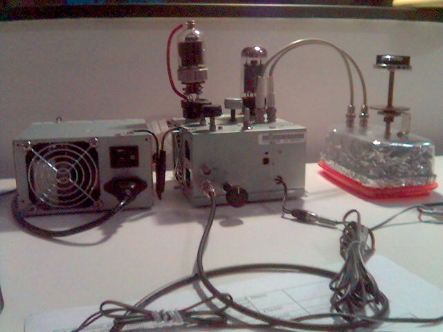
|
The resonant circuit of the VFO grid has been put in a separated shielded
enclosure, following the approach of
http://faculty.frostburg.edu/phys/latta/ee/wing2e26xctr/exciterpics1.htm.
So, as apparent from the picture, the rig now has one additional box
which just contains the said resonant network (and nothing else; the tubes
are still in the original chassis). A plastic container for storing cheese in the fridge has been sacrified for the additional box; the shielding has been obtained by squeezing a single-use aluminium baking tin into the container. Click on the pic for enlarging. |
|
The improvement obtained by this simple modification is huge. Indeed, this
time the oscillator is much less sensitive to the load on the final tube,
and gets no heat from the tubes so it is thermically more stable.
Problems:
The mechanical stability of the new shielded box is unsatisfactory. The VFO frequency varies unpredictably when turning the knob of the variable capacitor, due to the mechanical flexure induced in the box and in the capacitor itself.
Some coupling between the final and the VFO still exists. At least it seems so, since the transmission frequency still varies when tuning the plate variable capacitor. Maybe the coupling is between the final pi network and the inductance of the frequency doubler (placed at the grid of the final).
An annoying thermal drift during CW operation still exists. More precisely,
the VFO frequency increases during keying, and subsides during stand-by. After
a number of experiments I could find that this drift is caused by the change of
plate load on the oscillator tube during keying. Changing plate load causes
the plate current to change, and this in turn modifies the tube temperature
and, ultimately, the resonance frequency. If it is so, then adding a
buffer stage would solve.
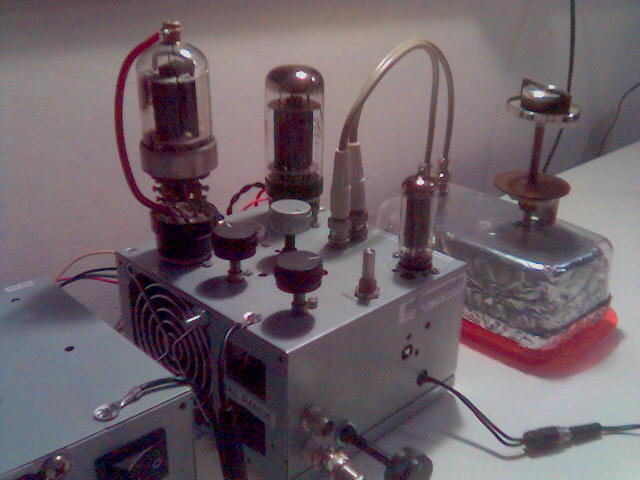
|
Three-tubes rig. The small tube visible in the picture is a 6CL6, for
the oscillator. The medium one is a 6L6 WXT+, for buffer/driver, and the large
one is the usual 6146B final. This is a decent rig to operate with,
although not perfect of course. Click on the pic for enlarging. |
|
As anticipated, the addition of a buffer stage hugely improves the thermal
stability of the VFO. The buffer acts as a more or less constant load on
the VFO, thus preventing the plate current of the oscillator tube (and thus the
tube temperature) to vary during keying. See the schematics.
So, as of today, I operate with a classical three-tubes configuration.
Some people might wonder why I did not do this way since the very beginning.
But remember: I'm a nerd! It was important for me to understand why
three tubes were really so necessary for decent operation, and how simpler
configurations with fewer tubes could still be operated.
|
Same three-tubes rig, but now the resonant circuit of the VFO is enclosed
and shielded into a more rigid aluminium can. Click on the pic for enlarging. |
The aluminium can partially solved the mechanical problems encountered with the previous shield, besides having a better look. You can also look at the rear of the can, as well as the inside.
With this solution, it is important that the rotary shaft of the variable
capacitor is insulated in the section where it crosses the shield.
Without insulation, the VFO frequency changes irregularly while rotating
the knob, due to imperfect electric contact between the rotary and the shield.
When insulation is in place, however, the frequency changes smoothly.
Better solutions are possible of course, this is just the simplest.
|
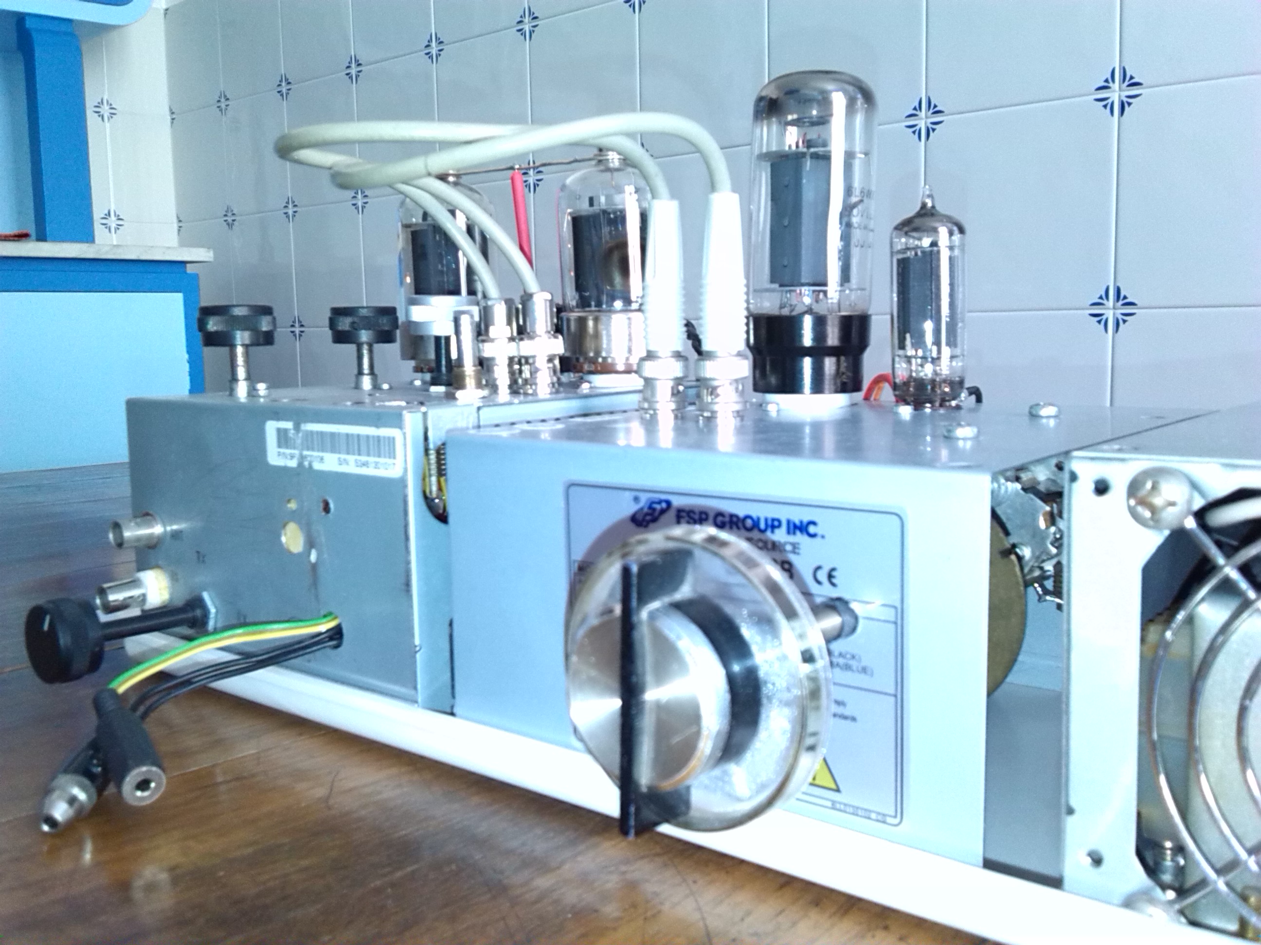
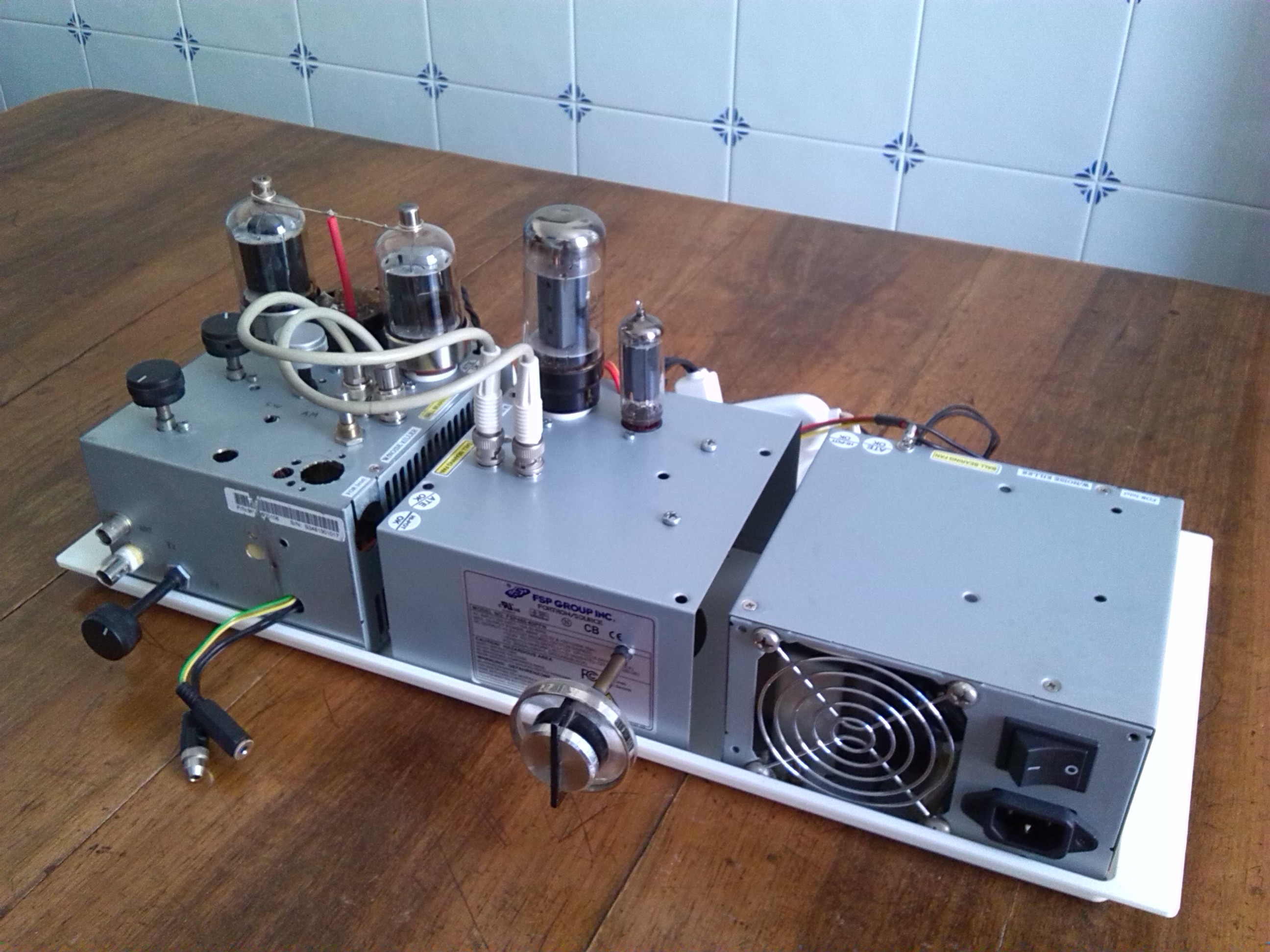
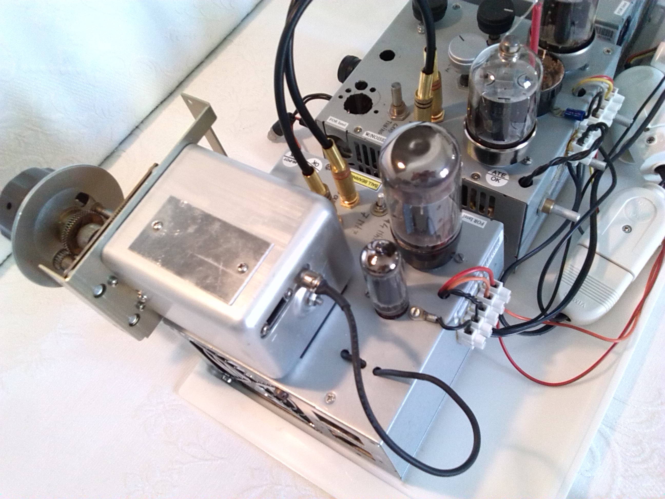
A more powerful rig, similar to previous one but with two 6146 final tubes in parallel. This rig yields an output in excess of 100 watt. Click on the pic for enlarging. |
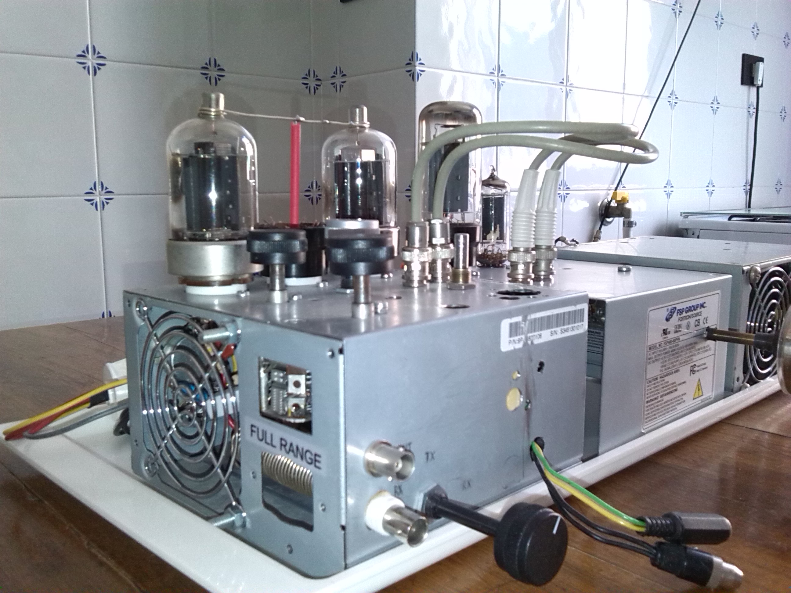
|
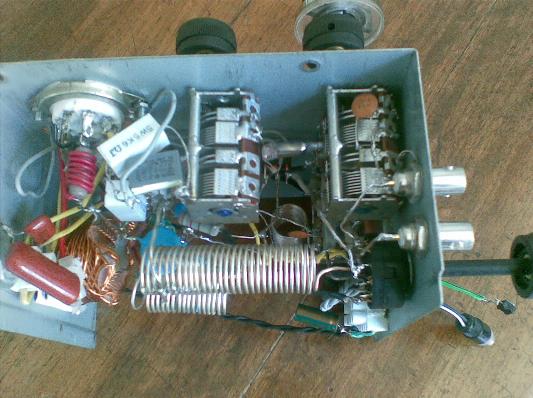
In order to host the second final tube in parallel to the first one, I had to split the rig into two chassis, one for the VFO/buffer and the other for the final stage, in addition to the power supply unit. Thus now the VFO resonant circuit is no longer separated in its own separate box. Here is a view from right and a view from above.
Overall, the circuit has only minor changes compared to previous one. See the schematics. It turned out that the two 6146 tubes were substantially different from each other, despite the same look. So the circuit provides two separate grid bias potentiometers, to be regulated individually so that, when operated by the input signal, each 6146 tube will draw the same plate current as the other.
|
An important finding is that the VFO is more stable if its enclosure is left open, like in the picture. One reason is that an open box dissipates the heat better, thus reducing deformation of the (too) flexible can. Another reason is that the open box has no metallic floor; thus, the capacitive-sensitive parts of the resonant circuit will not experience a change of capacity when the distance from the floor changes due to heat (of course they must be well fixed to the ceiling, otherwise they might experience a change with respect to it). In the picture you can also see the insulation of the rotary shaft where it passes through the box. |
|
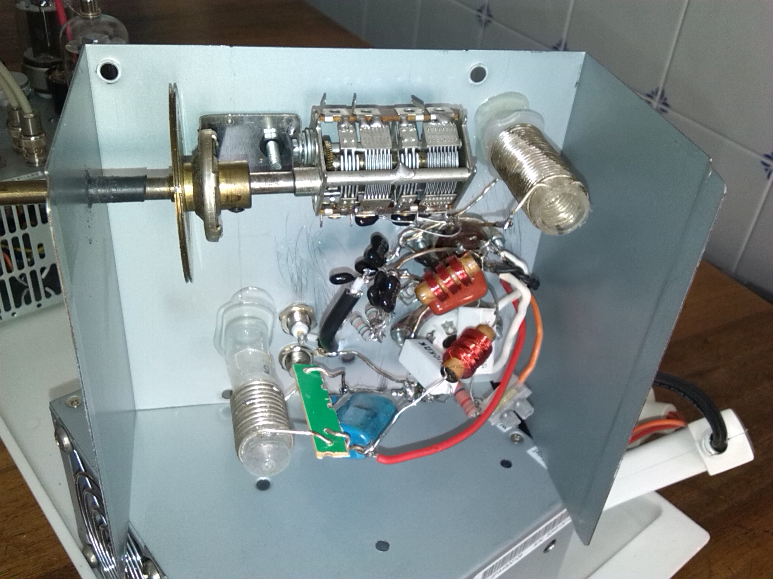
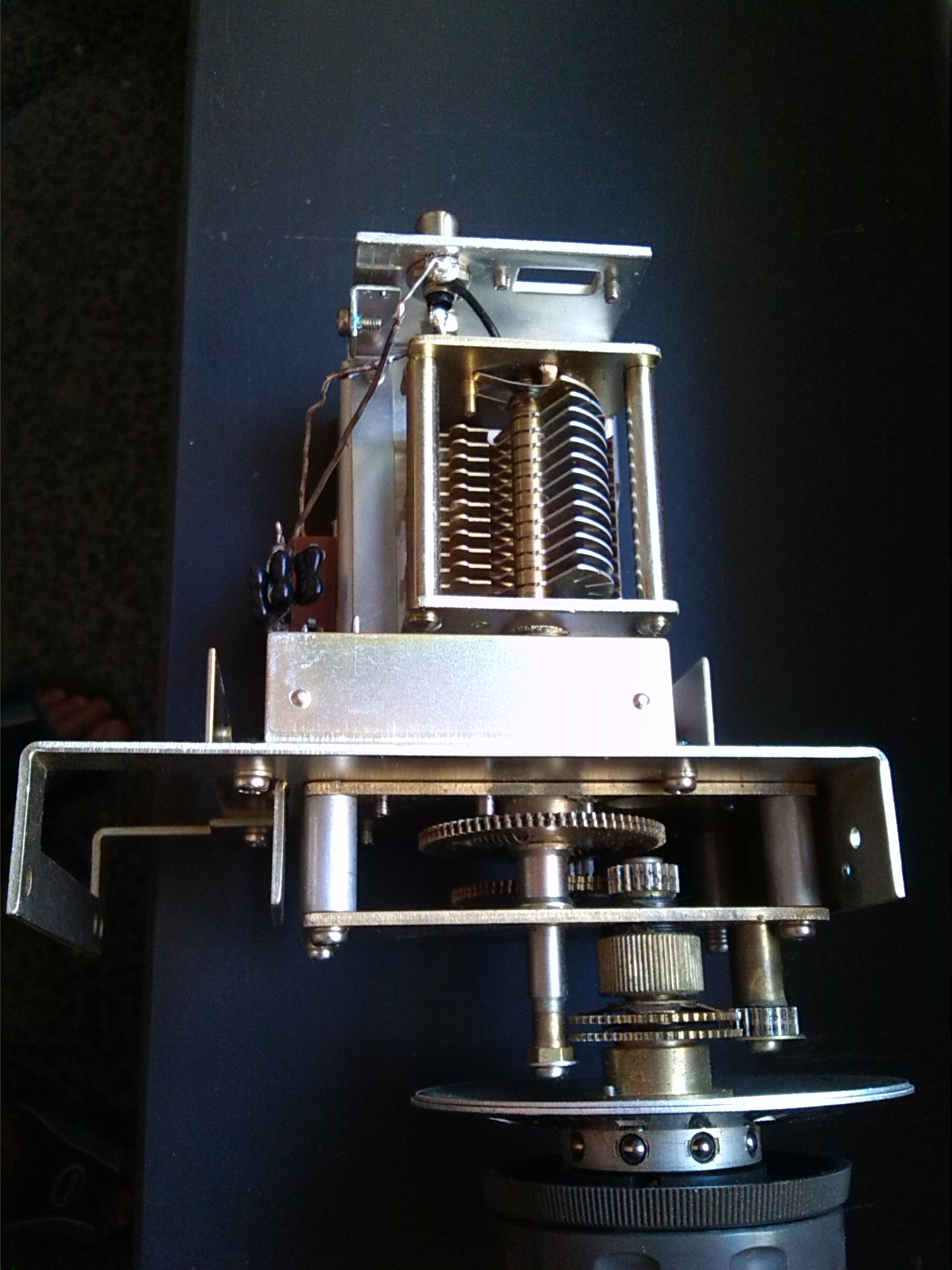
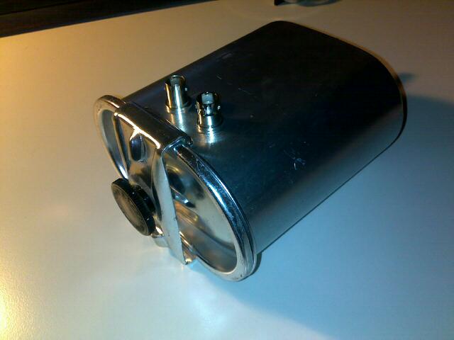
A more stable rig, similar to previous one but with a robust mechanics for the VFO. Click on the pic for enlarging. |
|
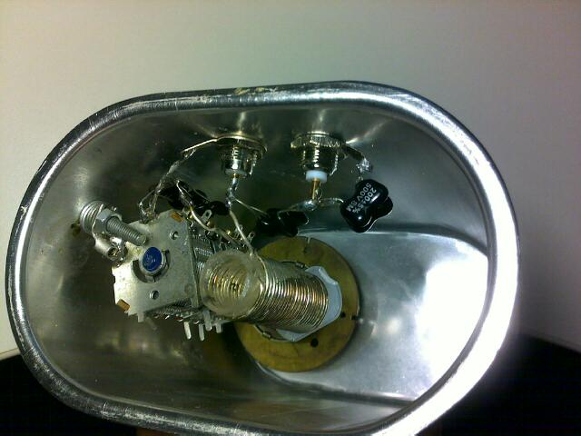
I happened to get the remains of a broken Kenwood TS-820 rig, courtesy of Mario Pieri I1PIM. The VFO from that rig was still working. After removing the internal circuitry (which was built around solid-state components) and replacing the inductance, I got a mechanically stable tank circuit for my VFO. The thick aluminium enclosure with the knob, containing the tank, is visible in the front picture as well as in the picure from above.
The obtained VFO has only a minor thermal drift and no more sudden frequency shifts.

|
|
Two views of the inside of the tank, showing an air variable capacitor with well-distanced plates, the impressive system of rotaries, and the rear room containing the self-made inductor and a trimmable capacitor for fine adjustment of the frequency range. |