 |
|
Figure 1 - The Circuit Diagram |
Are you suffering from TVI? Then why not try this filter for size. It is a
three-stage high-pass filter that blocks low-frequency 50MHz signals while
letting through UHF TV.
It has been designed to be placed in the 75 Ohm
coax between the aerial and television set or (masthead) pre-amp. In its current
form it cannot be placed between the television and pre-amp as this cable
usually carries +12V DC to power the preamp. A look at the circuit diagram will
tell you that it cannot pass a DC current!
|
|
Figure 1 - The Circuit Diagram |
The parts required to build the filter are as follows:
 |
|
Figure 2 - The Circuit Board |
The circuit board is made from a small piece of 0.1" Veroboard with the
centre tracks removed with a 5mm drill. The connection pads are isolated in the
same way. MAKE SURE THAT
THERE ARE NO SLIVERS OF TRACK LEFT IN THE
MIDDLE OR ON THE EDGES OF THE BOARD. These will act as capacitors bypassing the
filter elements and thus ruining the attenuation of the filter. The component
layout is shown in Figure 3. Ensure that all the leads of the components are as
SHORT AS PHYSICALLY POSSIBLE.
 |
|
Figure 3 - Component Layout |
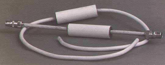
As far as mechanical assembly is concerned, thread the two short lengths of 75 Ohm coax through the two tap washers (middle holes enlarged) and through the inside of the plastic tube. Push the two washers into either end of the tube by 3mm and fill the ends of the tube with Araldite to seal against moisture ingression. Use tape as well if used outdoors.
 |
|
Figure 4 - Mechanical Assembly |
If the filter is to be used internally, connect the in-line plug and socket
to the ends of the leads. If it is being used at the masthead (the best place)
make the leads 1 metre in length and connect between the aerial and the pre-amp
input.
The measured attenuation of 50MHz signals is 70dB on the inner
core. You might need to use a braid breaker as well in some circumstances. How
one of these is designed and built will be shown in a future SIX NEWS.