This is the project for a 10Ghz Wide Band Frequency Modulation (WBFM) Transceiver using as microwave source a cheap Gunn diode cavity. The receiver part is also very simple as the modulator part and both can be built "junk box" components, as I have done.
This page is actually "work in progress" ( ![]() ): I will have to add some sections (antennas and preamplifiers) and to add photos of my xcvr. Tnx for your patience.
): I will have to add some sections (antennas and preamplifiers) and to add photos of my xcvr. Tnx for your patience.
It do not promit impressive performances, at least in its basic form, but is all the same able to cover a distance of a few miles with a little horn antenna or a little dish.
The Gunn diode has been developed by John Battiscombe Gunn, an Egyptian phisyc who discovered the effect that bring his name in 1942.
Gunn diodes are used as transferred electron oscillators (TED) by using the negative resistance property of bulk Gallium Arsenide. They were employed as microwaves sources in many ways including Home burglar alarms, but the progress in solid-state microwaves electronics has substituted these devices, that are now sold at really low prices.
In the modules that we are going to use in this project, Gunn diode is placed in a waveguide cavity, together with a mixer diode (tipically a 1N23 microwave diode).
The general scheme of a Gunn cavity is shown in figure1.
figure 1
The modulated DC is applied at the DC Bias point to modulate the output signal in the Frequency domain.
A part of the signal goes to the mixer diode, that produces an IF, mixing this signal with the incoming signal. The IF produced tipically goes from 1 to 200 Mhz.
The IF value choiced is also the difference in the TX freqency of the two transmitters (is like working in SPLIT mode on HF).
So a typical RTX is made of a modulated PSU and a FM detector set at a proper IF (typically 30 Mhz). Amplifiers, filters and converters are optional and could only enprove the performances.
In this kind of project we will use a surplus Gunn cavity (Any type is good).
It can be found in one of the many ham flea markets or bought on the net (see my Links page). The only problem is that if you need to place it in the focus of a dish, you will need a single waveguide cavity (i.e. a cavity in wich the two diodes are in the same waveguide). I have tried both types, but for this project i've used a Microwave Associates cavity with a standard flange and a standard WR90 guide. This make me able to link it with many types of antyennas and amplifiers, but an alarm cavity will work as much (figure 2).
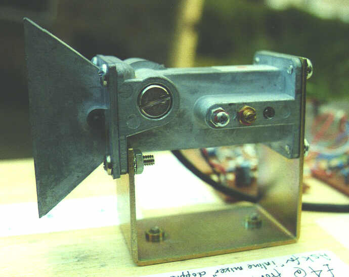
figure 2
In your module you will find two soldering pins and a little screw: one of the two pins is the Gunn Bias piont, the other is the mixer diode output, whereas the screw is the Gunn cavity mechanical tuning (you do not have to adjust this). Ensure to connect the external devices to the right pin looking to the schemes (if they are provided) or by looking in the cavity: the mixer diode is a little white ceramic cilinder, but it is not visible in all cavities (in mine it isn't).
If your module has a flange, you can connect it to other MW devices (such as Klystron or TWT amplifiers, circulators, LNA etc...) with a piece of waveguide.
This device transforms the voice of the operator in a variable voltage, that is to be applied to the Bias point to obtain an FM transmission.
Infact the output frequency generated by the Gunn diode depends on the voltage applied to it, but also the output power (tipically 10 mW).
In figure 3 you can see the scheme of the modulator.
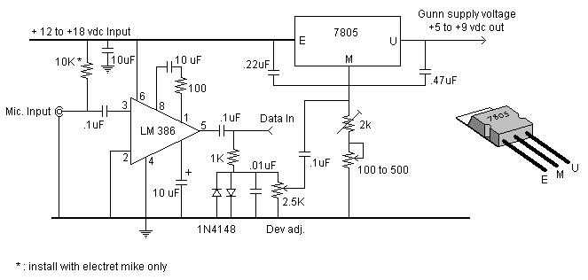
figure 3
It is nothing of particular: a LM386 amplifies the signal of the microphone, that is applied thru a resistive network to the 'heart' pin of a 7805 regulator. This arrangement make the 7805 an adjustable regulator and the output voltage is controlled by the amplified audio signal. The output voltage shifts around 8V.
To set for the best performance you have to adjust the deviation potentiometer and the two trimmers.
The input 'DATA IN' is provided for digital communications as computer networking (see my Links page)or for ATV together with a video amplifier.
The layout is not critical and I've mounted it on a prototype board.
I was looking for a simple receiver, that could in case be modified and improved. I've discard multiple conversion receiver for a simple TDA7000 receiver. This is a project of Peter Day, G3PHO, I've just replaced the LM380 audio amp with a LM386.
You can see the RX scheme in figure 4.
figure 4
Finally in figure 5 you can see the audio power amplifier.

figure 5
I recommend to enclose the RTX in a metal box. If you need to use a dish antenna you have place only the cavity in its focus, connecting it to the RTX with a coaxial cable. Yuo can also put the cavity into the box to reduce dimensions.
To set up you transceiver you can follow the procedure shown in G3PHO site, but I have a simplest way to made it: buying two modules!
In fact you can use the Gunn diode of one as generator, and the mixer diode of the other to test the RX. To use the Gunn diode as carrier transmitter you have just to apply 8Vcc to its Bias teminal with a 100nF bypass capacitor to the heart.
Another way is to built my simple 10Ghz frequency marker that uses 1N23 MW diode.
 I'm actually working on this section. I'll update it as soon as possible.
These modules works on the band of 3cm from 10,000 to 10,500 Mhz.
The power is usually low (10mW) but some types outputs 100mW.
So it's not a good idea to look into the cavity while it's working or staying in front of the antenna during a QSO...
Remember what happens to chicken when it is in a microwave oven...