FLAT HELICAL ANTENNA - ELICOIDALE PIANA
(by is0iek - 1979)
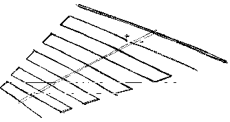
I thought that a broad bandpass directional radiator may be achieved with a progressive wave along a conductor, as in a long-wire antenna, bending the conductor into "turns" ; and progressively reducing spacing between them, together with the length of each as in a
log-periodic array, the longest of them having a half-wave length at the lowest operation frequency. Strictly speaking of "turns" will be improper, the whole antenna being a flat structure, laying in a plane.Flat helical feeding schematic - schema di alimentazione
Currents in adjacent turns having fitting spacing and size will enforce radiation in the end-fire direction, while from the other turns it will cancel, as well as in other directions ; forming as a result an "active region" which can slide along the array varying the operating frequency, nearly the same as in a log-periodic.
Some doubts may involve the feeding point, impedance, phase and intensity of current in each turn in relationship with power feed into.
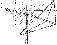
I've experiemnted just a bit such arrays in 1979 in HF (fixed array) and VHF, discovering that almost in the VHF model, maximum radiation was not in the end-fire direction, but at an horizontal angle about 135° with it, and in the HF model radiation occurred at a fairly high vertical angle, that perhaps because of insufficient structure height vs. roof, and incorrect choice of feeding point.

Ho pensato che un radiatore a larga banda passante con caratteristiche direzionali potesse ottenersi mediante un'onda progressiva lungo un conduttore, in analogia a quanto accade nell'antenna long-wire, piegando e ripiegando il conduttore a formare delle "spire" ; riducendone progressivamente le dimensioni e la spaziatura relativa, come in una
log-periodica, la maggiore di esse avente dimensioni lineari pari a mezz'onda alla frequenza operativa più bassa. Parlare di "spire" in senso stretto sarebbe improprio, formando l'intera antenna una struttura piatta, giacente cioè in un piano.Rotating array project - progetto di antenna rotativa
Le correnti nelle spire adiacenti, aventi dimensioni e spaziatura adatti, contribuiranno alla radiazione nella direzione desiderata, lungo la struttura (end-fire), mentre dalle altre spire tenderà a cancellarsi, come pure nelle altre direzioni ; formando come risultato una "regione attiva" in grado di scorrere lungo la struttura, in modo pressoché analogo alla log-periodica.
Alcuni dubbi possono riguardare il punto di alimentazione, impedenza, fase ed intensità delle correnti in ciascuna spira, in rapporto alla potenza in essa introdotta.
Ho sperimentato un tantino antenne siffatte nel 1979 in HF (direttiva fissa) ed in VHF, scoprendo che la maggior parte della radiazione andava, almeno nel modello VHF, non nella direzione frontale ma in una formante un angolo orizzontale di circa 135° con essa, e nel modello HF ad angoli verticali piuttosto elevati, ciò forse a causa della insufficiente altezza della struttura rispetto alla terrazza, ed alla scelta di un punto di alimentazione inadatto.