 |
 |
|
|
|
|
|
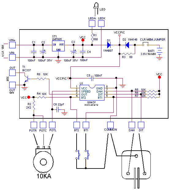
R1...........680 R2...........2K2 R3............68 R4-R8........10K C1,C4,C5...100nF C2,C3...100uF35V C6..........22pF D1........1N4007 D2........1N4148 T1.........BC337 BAT1..3.6V NI-MH JUMPER......2PIN ST1.......LM7805 U1.........DXKEY POT.........10KA LEDA-K.......LED BT1-BT2...Key NA DAHDIT.Iambic KEY N.B. The Jumper CLR MEM |
|
|
|
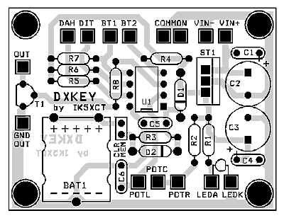
Photo not to scale. PCB measures 6.0 x 4.5 cm. (2.36 x 1.77 inches) |
|
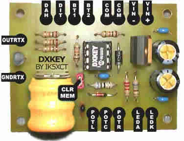
This view is not to scale. please use the PDF for correct sizing |

|
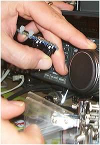
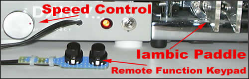
This special function keypad is operated easily with the index finger and thumb of the free hand. It is remote from the keyer and enables you to operate and even tune the TCVR simultaneously. |
 |
 Ritorna alla Pagina Principale