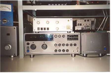
| src-93 transceiver, speaker and 144Mhz 30 W. transverter |
 |
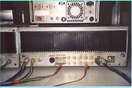
| src-93 rear view: a large heat sink. Above rig is TS570DG |
 |
| HF Transceiver
SRC-93, analogic HF amateur bands only, 100 watts out, home made TRX
with 28-144 MHz transverter (home made in 1993 by I4FAF). Some more details: First IF: 10.7 Mhz with quarz bandpass filter; second IF: 9 Mhz with quartz bp filters with pass band tuning and third IF at: 455 Khz with more band pass filters. There are 9 amateur bands only passive antenna input RX/TX bandpass filters with relays for band changes. A pushpull 2x2n5109 CATV linear transistors RX 12 dB gain broadband preampl. which can be bypassed (the so called "IPO" position when not in line). The first mixer is a High Level diode doubly balanced ring mixer. A "17Super" level by Mini-Circuits, model TAK-3H, at +17dbm of local oscillator power, closed in all ports with 50 Ohm (diplexer at IF side) for improved Spurious Free Dynamic Range (SFDR) and input sensitivity. The VFO (A and B two are available for inband split operation) is a very clean "old style" 3 Mhz to 3.5 Mhz LC with a good air variable C frequency control (increasing VFO frequency we get a direct increase in received frequency tuning), mixed with 9 different, band related, fixed quarz oscillators with each output band pass filters to get the proper sum frequency (at +20dBm) to be injected (Band frequency + 10.7 Mhz) at the local oscillator first mixer input via a -3dB 50 Ohm resistive pi attenuator. Example for 20 meter band frequency chart: tuning capability 14.0 Mhz to 14.5 Mhz in to first mixer RF port, Local Oscillator injection frequency is 24.7 Mhz to 25.2 Mhz, so 24.7 - 14.0= 10.7 Mhz first IF, and we get it as sum result of mixing a fixed quarz oscillator at 21.7Mhz + VFO (3 to 3.5 Mhz) and band pass filtering of this sum frequency). Some minor stability problems are to be expected while operating CW, but on phone it is not a big problem. To avoid this problem you could try to use the fine synthesizer DDS-PLL with VCOs as similar to the one described with double tank in RADCOM (RSGB) october 2002 in the article series by G3SBI, G3OGQ, G8KBB high performance trx "CDG2000". The transmitter has an IF RF clipper and the RF 100 watt (average or CW power) final is around a Motorola RF application note AN762 (See schematic and list components available from Communication Concepts, Inc (in USA) a with rugged 13.8 V 2x MRF421 <---- click here for data sheet, with a large heat sink in the back side of the equipment. The driver is also a push-pull transistors configuration (very similar to the one in the CDG2000 Web site). The modulator and product detector are built around SO42P IC by Siemens (a Gilbert cell type IC mixer). More than 10.000 qsos has been made in the past years without any single problem. |
| src-93 transceiver, speaker and 144Mhz 30 W. transverter |
 |
| src-93 rear view: a large heat sink. Above rig is TS570DG |
 |