|
scheme.gif (3500x2400 -> 249k) |
|
|
|
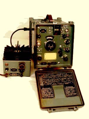
R326 with AC power supply |
|
|
|
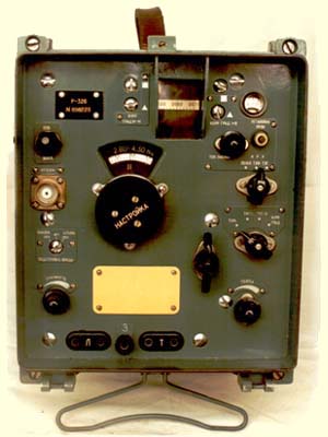
Front view |
|
|
|
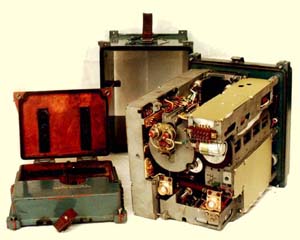
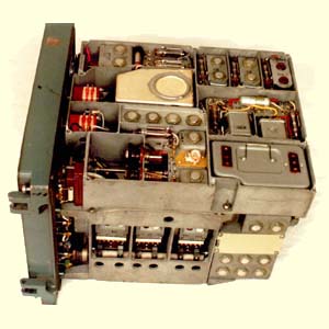
Open box |
|
|
|
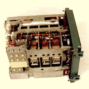
Left view |
|
|
|
Right view |
The end of the spring time brings the local hamfest to Torino, North West part of Italy. The Radio Expo Torino is organized by a technical school and is located in a building at the city exposition center It's mainly an exposition of commercial equipment and components related to hams. It begins on Saturday morning and I was at the opening gate to enjoy its 9th edition.
During the first scanning between the tables I got two original boxes of 120 FT-243 crystals for $6 each, a good start! Then I saw some CPRC-26 (Canadian walkie-talkie) at $30 and a GRC9 at an incredible $400!
Looking around there was a lot of modem silicon, plastic housed, but that is not so interesting to me.
An Italian popular electronics magazine had the good idea to show working models of the first Marconi radios. It was unusual and wonderful to see a spark transmitter of that kind.
After four hours of walking around I was just ready to go home. Then on the rear of a table I saw some metallic boxes of the dimension of half a BC-348, painted in light cyan-grey color, completely closed. The seller told me they were Russian HF receivers, nothing more. Looking at one of them I opened the front cover and saw a square optical film ocular and some Cyrillic labels. I was attracted by the mechanical design before knowing of the electronics inside. The price agreed seemed to me a bit risky, but the look was exotic enough to lead me to buy. Together with the box I went home with a bad photocopy of the electric schematic and the original AC power supply. The real discovery of the radio started at home.
My very patient wife and children (our first harmonic Paolo is IK1YMP, the three daughters are not yet 'neutralized') recognized the 'tight pistons' disease and gave me the Saturday afternoon time to play with the radio.
I was careless and I connected head phones and switched it on, without any precaution The R326 or P326, depending on Cyrillic alphabet, glowed and the audio started immediately;y in a few hundred milliseconds. I was surprised a little because of the fast start while the schematic shows all tubes, but the article by N0DMS, "The Forgotten Science" in ER #73 I had just read, helped me to understand the miracle. It uses 19 miniature tubes with direct heating in all the functions except for the DC-DC converter and the external AC power supply stabilizer that uses three germanium power transistors. After the first cleaning and power checking, the R326 radio continued to work perfectly as at the first try.
The schematic shows a double-conversion super heterodyne receiver, covering the 1-20 MHz range in the following bands: 1-1.92, 1.92-2.8, 2.8-4.3, 4.3-8.7,8.7-12.0, 12.0-20MHz. The first IF is at 2.2 MHz or 460kHz and the second at 215 kHz. The radio label is "P-326 N 898226". I was not able to find any date inside but I suppose it was designed during late '60's.
The design uses two RF stages. The first mixer heterodynes the input signal with the buffered variable oscillator output. Each of the stages has a tuned circuit The band change mechanism is based on a rotary drum similar to the SP-600, but smaller. Each input tuned circuit has a trimmable inductor and capacitor, while the oscillator components are not placed on the rotary drum. The RF stage tubes are inserted through the separation shielding. The oscillator inductors and capacitors are inserted into the double-shielded oscillator compartment. These inductors don't have trimming capability. A second mixing stage converts the signal of the first IF amplifier to the final IF, that includes a variable selectivity filter.
The front cover has a tuning control, a band selector, an AGC selector (off, AM, CW-SSB), a mode control (AM, CW-SSB variable BFO, CW-SSB fixed BFO), a BFO tuning control and dial (+1-3 kHz), a gain control and a selectivity control (continuous from 300 Hz to 6 kHz). On the left there are the antenna connector, an input antenna trimmer and the dial light switch. On the lower part of the front panel two output sockets carry the demodulated audio signal at an output impedance of 600 Ohm. At the first look at the front panel, I confess that I assumed the lower left knob to be the volume and the lower right one to be the RF gain, because it looked like a potentiometer. Turning it and looking at the schematic I realized that the gain control works at IF and RF level only. There is no volume control. It forces the operator to use the detector at the right level.
The right knob is a selectivity control acting on a single quartz filter with a double-tuned circuit. The other six tuned circuits shape the actual selectivity. The knob controls a gear that operates two variable capacitors with opposite spins. The effect is a very pleasant, smooth, variable selectivity control.
The R326 is a very rugged piece of equipment. The radio is housed in a metallic molded case with detach able front cover. A top leather handle helps to move its 12 kilo.
On the rear a Bakelite holder opens to house two batteries. The operating voltage is 2.5 volt with 1 A drain, (yes, 2.5 Watts!!). The two batteries were probably of nickel cadmium type. The size suggests some ten amps capacity. Luckily, the AC power supply feeds the radio also without the batteries. The radio is fully and heavily shielded and all the mechanical design is really wonderful you can imagine that a signal tuned at 20 MHz returned to zero beat after a band change, with a precision far better than 100 Hz. The frequency drift is less than 100 Hz/hour.
The shielding is so effective that I was not able to detect any radiated signal, oscillator, or BFO going out from the radio.
All the controls are sealed using a leather pressed ring tightened with screws and a metallic pressure ring. All the labels are written in Cyrillic, using a removable marker; probably a way to adapt the radio easily to operators of different languages. In fact the electric schematic I got shows some words in a Latin alphabet, Latvian or another similar language.
The tuning control is good also in SSB and CW, a two-speed epicyclical knob drives the tuning gears. The dial behind the tuning control offers just a rough frequency indication. The fine one is obtained with a film projection from the rear of the equipment to the front ocular. The lamp on the rear can be switched off, for night operation, while a second lamp is ready to operate by just turning an external control for back up.
Close to the fine tuning indicator there are two pairs of adjustment screws, used to align the oscillators and the tuning dial. Two, because imaging and other tricks allow the oscillator to use only two fixed inductors and trimming capacitors. I suppose that the screw that moves the ocular dial reference operates instead of inductor trimming for the dial tracking.
The radio has no calibrator inside, while the dial has 2 kHz marker spacing on 80 meters and 10 kHz on 20 meters.
Going inside the radio, I realized the most astonishing fact. ALL the IF inductors are fixed using a heavy solder point, that looks quite impossible to remove without destroying the inductor itself. I am trying to get the technical manual, via some Russian ham, to understand if there is a provision for re alignment, and in which way. The unit I got is performing very well without any re alignment. I suppose this solution has been implemented against vibrations or against spurious radiation.
On the back of the radio, internally located, there are two connectors that carry out the first IF, I suppose for a panoramic display, and the output of the second IF, I guess for different demodulators.
There are some minor drawbacks: no signal strength indicator exists and an annoying whistle comes from the internal DC-DC converter (transformer?), that at the moment I have not been able to fix.
AM reception is fine and in SSB the radio sounds to me better than modem receivers like TS50 or IC725. I suppose that the less sharp filter has a lower group delay distortion. I don't know if it's true, but starting from June '95, R326 is my preferred all-mode receiver.
To make a long story short: on Sunday I went to the exhibition again to buy the second R326 for spare parts and future maintenance.
30 Dec 2009 update: Ed PAoMIV sent me a scanner image of the Russian manual and diagrams.
R326.pdf (Russian Manual 24MB)schema01.jpg (4.9MB)
schema02.jpg (2.7MB)
schema03.jpg (14.9MB)