In this page it is possible find informations
on Power supply, some additional information on the set lately arrived and
finally the message boards with many Questions and Answer.
The Message Boards in many cases will
clarify some doubts and will help to solve some practical construction
problem
First release 01/03/02
PSU
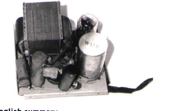
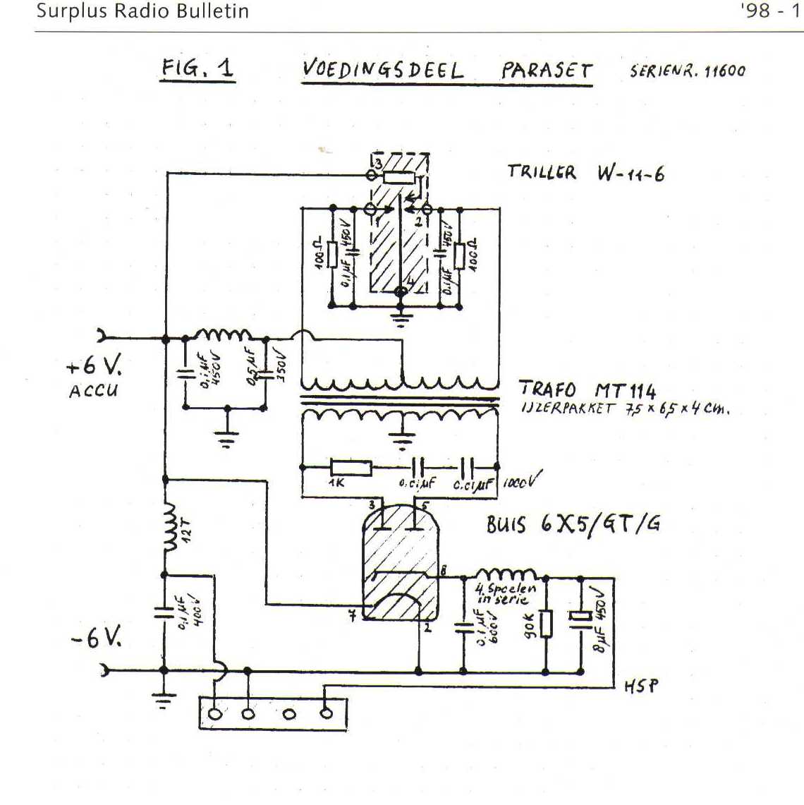
As said at the begining the Paraset PSU were vibrator type supplied to 6 Vdc. Below some internal photos of the original set (source ON9CFJ)
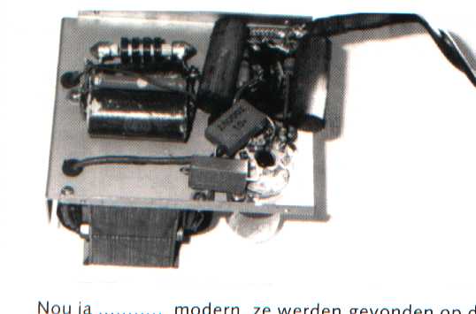
and in addition clicking here you can
get the schematics (ON9CFJ Originator)
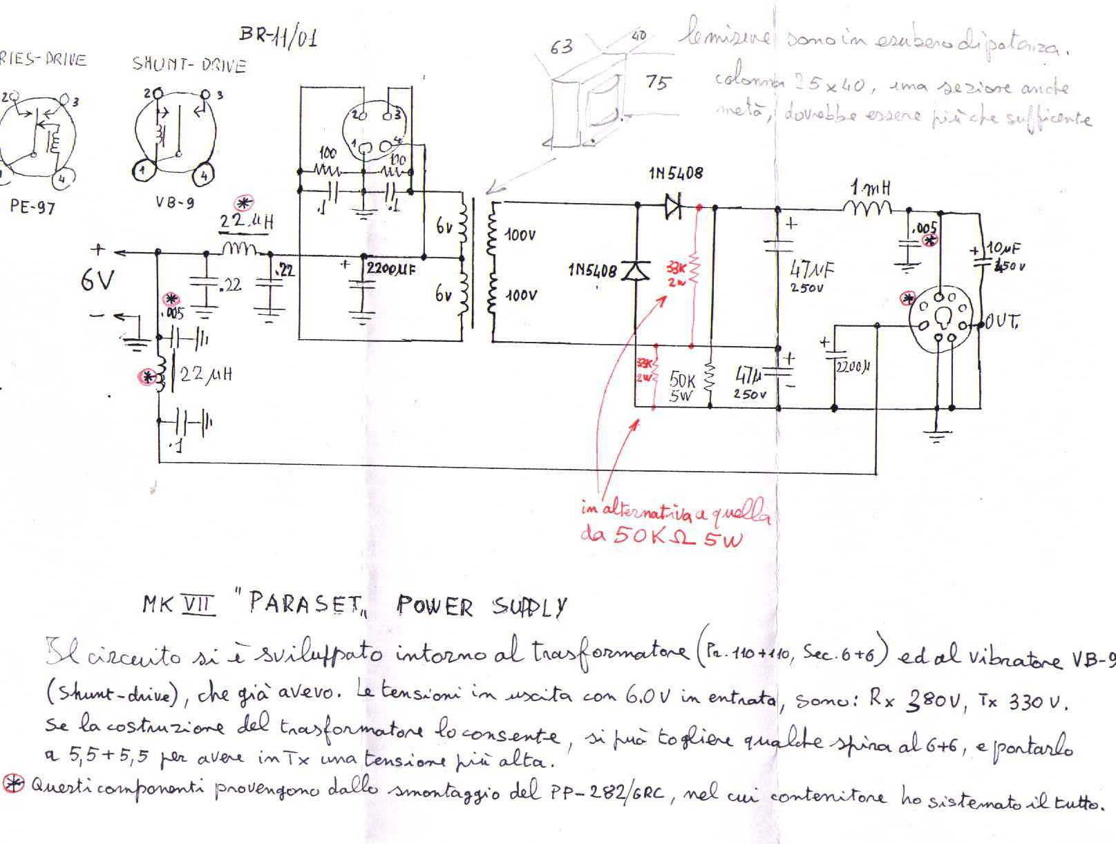
In the 3 sets built in Italy has been used AC power supply using some old radio set transformers, rectifiers and simple filter capacitor. The sets are properly working also with 300 Vdc (HT voltage).
Roberto - I0BR built also replica of the original
PSU with fine results. The PSU has been enclosed in a PP281 box and looks
very fine. For the diagram and notes click
here.
MESSAGE BOARDS
From PA0VYL
Dr. Mario,
Many thanks for your email. I shall ask a friend to make some electronic pictures
of our Paraset and send them to you by email. If you like to see an original
of the Paraset you only have to visit our (small) museum Hi.
Did Jo, ON9CFJ send you the drawings of the set?
Our Home page is: <http://www.des.nl.ws19/index.html>
73, Cor Moerman PA0VYL.
From ON9CFJ
Hi Mario,
re 1. The 3 pin connector on the chassis or panel is female type.
The male part is connected to the cord. The 4 pin connector on the vibrator
P.S. is also female type (1 pin not used). So both male connectors are on
the cord (with 3 wires).
re 2. There are no feet on the bottom of the box.
re 3. There is no locking system on the case cover.
re 4. The big PA coil is fixed with 1 stand off and 1 brass bolt and
nut. The stand off is on one side flat and on the other side curved to fit
the coil. The coil is 7 mm. above the chassis (or panel). The 3 mm. bolt
is countersunk through the panel, so you can see it on the top. The bolt
is positioned between the two wire coils on the former.
Again do not hesitate to ask more questions if necessary
Best regards,
Jo, ON9CFJ
From IK5FUZ
Ciao Mario,
Let me have alla info you have. I used bakelite sockets taken fron an old
TV sets.
The TX worked immediately with an output of 5 W. Take care about the
set layout because there many mistakes. Follow the electrical diagramm thet
is correct.
About the 36 H impedance I tested several value of inductance and
also a 2700 Ohm resistor. The only difference is in the AF level in output.
I tested some TV cristals with poor results
73 de Alberto
.
From W1HIS
Thank you for posting such a good description, with so many good
photographs and good detail. Very interesting project, and you have
done very nice work. I am sorry that my mechanical skills are so
poor, that I am unable to undertake such a project.
Let me know if ever you would like to try a transatlantic QSO with
your Paraset replica. In view of the simplicity of the Paraset
receiver, I would transmit high power (1500 W) to you.
73 de Chuck, W1HIS
From IK0MOZ
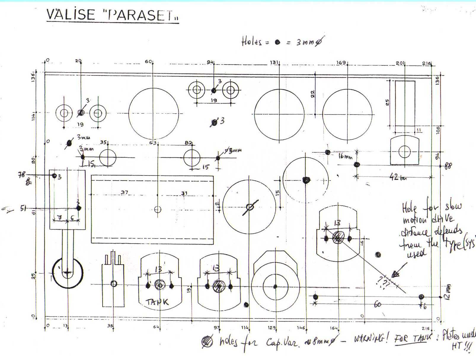
A to W1HIS
Here is my drilling template. Some holes position
is according the part in use
From ON9CFJ
Dear Mario,
After reading your e-mail with your new mail address today, i immediately
took a look at your website about the paraset project in Italy. I have downloaded
this side, which took quite a lot of time, but now it is inside my computer
so I can take a closer look afterwards. But i want you let know that my first
impression is very good. I am quite amazed how many details you are giving,
but the most impressed i am about the very realistic looking replicas which
have been built.
I have to congratulate you and your team members whith the outstanding results
you achieved in such a short time, and i am happy that i was in the opportunity
to give you some little help.
Keep up the good work Mario and, again, do not hesitate to ask me if there
are any more questions.
Best regards, Jo, ON9CFJ
Q from IK0MOZ and IK5FUZ
Hello Jo, we hardly working on Paraset Project and 3 sets are near the finish
line. Unfortunately in each step there are some problems. Here some questions
:
1) Please let me know the pin out of the PSU connector starting from the
high (LT-Ground HT ???)
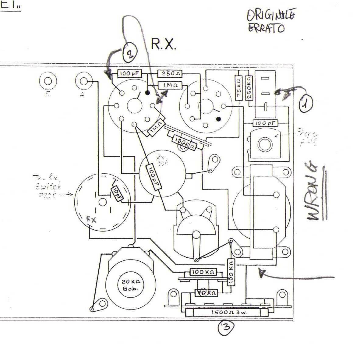
2) In the RX layout you sent me there are many mistakes
a) Connections to 3 pin connector wrong
b) Connections on the first 6SK7 socket wrong - some components connected
to filaments pins
c) Some value wrong.
3) There is something of strange on the circuit diagram. How is the Plate
voltages on 6SK7 tubes ?
4) In the photo you sent can be seen a big resistor - The value of this resistor
is 1.5 K or 10 K
5) I guess that the 3 W indication on the drawing is for the 10 K resistor
not for 1.5 K
Additional question : who is the source of the Paraset drawing you sent me.
This to give him right credit for his work.
I am preparing a web page for PARASET PROJECT, hope very soon on the net.
You will have a special mention..Hi...Hi...
Ciao and 73 de Mario - IK0MOZ
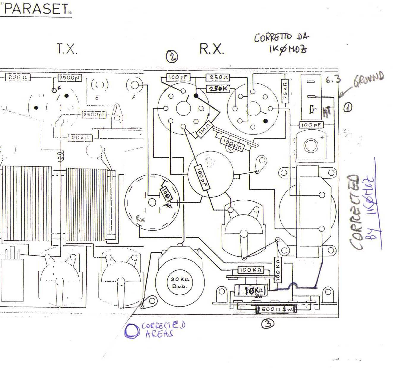
WRONG AREAS found in the RX layout
A from ON9CFJ
Dear Mario, Nice to hear again about the Paraset project in Italy.
Here are my answers to your questions:
re 1. The PSU connector has three pins: two horizontal pins and one
vertical pin. The middle (horizontal) pin is connected to earth via the phone
plug. There is a wire from this pin to the phone plug and from the phone
plug to earth. The other horizontal pin is for the filament voltage (6 volt)
The vertical pin is for the high tension plate voltage.
Remark: when using a home built mains supply with 6,3 volt AC for filaments,
then there is a hum in the receiver and in the transmitter note. On the 6
volt vibrator supply there is no hum because of 6 volt DC for the filaments.
re 2 a. Yes, connenctions are wrong on the lay out drawing. The middle horizontal
pin is connected to the phone plug and then to earth. The 250 K resistor
is not connected to the PSU vertical pin. The high horizontal 6 volt pin
is connected to pin 7 of both tubes 6SK7. So two wires are starting from
this pin to the filaments.
re 2 b. Yes, connections are wrong on the lay out for the first 6SK7 tube
(that is the left 6SK7 when looked from the underside). On pin 7 of the first
6SK7 is only the 6 volt filament voltage. From this pin is also starting
a wire to pin 7 of the TX tube filament(6V6).
re 2 c. I agree that the lay out drawing has several
mistakes. It is impossible for me to check the complete lay out because
in that case I have to remove many components from the Paraset to get a clear
look. You can imagine that I do not want to do so.
re 3. As far I have checked, the circuit diagram is wright as shown in my
article in the SRS-bulletin '98 - 11. Exception: the condensor from the plate
(pin 8) on the first 6SK7 to earth side of the crystal socket is 10 mmf in
stead of 100 mmf. I have checked the voltages in the receiver when using
the original vibrator PSU:
On switch on the supply voltage is 370 Volt on Rx load. Then the plate
voltage (pin 8) of the first 6SK7 is 239 Volt and on the second 6SK7 (pin
8) is 285 Volt.
After 5 minutes the supply voltage is 390 Volt on Rx load and then on plate
one 245 V and on plate two 296 V.
re 4. The big resistor is 10 K. Under this resistor and closer to the chassis
is resistor 1,5 K. The 10 K resistor is soldered between pin 1 and 5 of the
solder lug. The 1,5 K resistor is soldered between pin 1 and 4 of this solder
lug.
re 5. There is no wattage indication on the 10 K and 1,5 K resistor. The
10 K is in brown color and has an orange dot. Dimensions are: long 63 mm.
and diameter 14 mm. The 1,5 K is also in brown, but has a red dot and one
side is green. Dimensions: long 43 mm. and diameter 7 mm.
re additional question: The lay out drawing is made by ON5LJ. I do not know
ON5LJ personally and do not have his address, but got the drawing fron F5XM
who made his replica to these drawings.
I wish you good luck on the project. Best regards, Jo, ON9CFJ
From I0BR
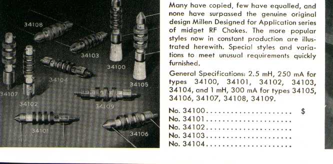
Mario, For experiment I changed the 2.5 mH RF impedances with two
1 mH impedances (same shape of the original). No variation on TX or RX performances.
Saluti I0BR.
RF Impedance : From an old J.Millen catalog
From F5CNK
superbe!!!!
Quel beau site sur le paraset
73 s de Chris F6CNK ex FR5DO
Q from VE1NU
I am looking for a 3 pin plug and socket, Cinch Jones or Cinch,
don't remember who made them. Same type that are used on the
19 set crystal calibrator. I am building a WW2 replica of a so called
Spy Radio and don't want to cannibalize my calibrator.
Anybody out there have a spare set they are willing to sell me ?
7 3 Reed
From VE1NU
Hi Mario
Looks like there are at least 3 of us on this side of the Atlantic that are
building replicas. Myself, VE1NU in New Brunswick, east coast of Canada,
Bruce MacMillan, VE7MT in British Columbia on the west coast of Canada
and Victor Politi, W1NU in Connecticut in the USA. By the way, we are all
users of the old Wireless Set #19 also.
Thanks for getting us interested in the Paraset project, and of course, many
thanks for all the information you have on your web site.
7 3 Reed Park
From VE3BBN
Hi Mario,
I just found your site and think it's just great. You did a beautiful
job building the parasets. The drilling template did not show the bolt
holes for the sockets or other parts and I was wondering if you have
this layout handy ? I can get away without it but I want to keep the
mounting of parts as close to what you have as possible.
thanks in advance David ve3bbn
From W1HIS - WS19 Group
........
The chief topic of discussion was possible new activities for the WS
19 Group in 2002. The three main suggestions were:
(1) an 80-m, evening, SSB voice net;
(2) WS 19 R/T operations; and
(3) building replica parasets as described by Mario, IK0MOZ, at
<<http://www.qsl.net/ik0moz/paraset_eng.htm>>.
Q from VA3ORP
Mario's project looks great. The
photo's on his website are wonderful and the final product is simply
outstanding. "BZ" to IK0MOZ!
Q from VE1NU
Hi Mario
I am looking for some additional info re the Paraset. On your web site,
there are a couple of broken links.
1c ) Case Drawing - All I get is "document contained no data"
2 ) Detailed drawings for key, coils, impedance's - The bottom part
of the page is cut off, so I can't see the outside dimensions of both coils.
I can read the
number of turns of wire OK.
8 ) Top Case (Originator ON9CFJ) - Once again, all I get when I click on
that link is "document contains no data"
I wonder if you could please let me know this information.
Many thanks Reed Park
A from IK0MOZ
Hello Reed
I also checked the pages and noted something not correctly working, I dont
understand why, but I will put newly the link.
I checked also the Italian version and this is correctly working.
Please check this possibility the position are the same also if description
is in Italian language, means:
1c ) for case , 2) Coils and key, 8) Top case
please note that for 8) Top case the drawing is .BMP format and need
"Paint" or similar program
Ciao de Mario - IK0MOZ
Q from W1NU
Dear OM Mario: Reed, VE1NU and myself, Vic, W1NU are in the process of building
the Paraset and we have some questions. What is the diameter of the TX and
RX coil forms , in MM, CM or Inches???. What is the wire size for the TX
and RX coils??., # 18, 22, 24,etc??. Also the 36 henry audio choke is a rare
item to find. I read where one of the builders used a Radio Shack transformer
and added some turns of wire to it. Can you tell me what the Radio Shack
number of the transformer or give me a description of it???. I have finished
the case and am well on my way to gathering the remaining parts as is Reed,
VE1NU. Any info you can give us will be greatly appreciated Mario. I am 79
years of age, a veteran of WW II and have been an active ham since March
of l939. Your Web page is great and thank you for getting us interested in
the Paraset project. In WW II I used all the army equipment, BC611,SCR-284,
SCR-188, BC-610, WS-18 and WS-19 from l942 through 1945 in North Africa,
Tunisia, Sicily, Italy, Normandy and Northern France campaigns. Its nice
that young men like you are interested in making this equipment work again
and keeping it on the air.. Ciao, Ciao es 73 de Vic, W1NU
A from IK0MOZ
Hi Vic, TNX for compliment always appreciated....hi...hi.
About you questions :
TX coil diameter 38 mm = 1.5 inch
RX coil diameter 25 mm = 1 inch.
TX coil form homebrew. using a tooth-paste plastic container. Many inner
part of reels (paper, wire.....) are of this diameter.
RX coil form I used a coil taken from an old BC610 TU
Wires: Tank 18 turns 1.5 mm about # 15; Aerial 22 turns 1 mm about # 18.
RX wire 0,6 mm around # 22
36 H Audio choke: Yes it is a very rare item, but there are many possibility
of replacement. I noted that starting from 18 H the RX works correctly. Like
first step I used a small AC trasnformer (3 W) 230/6 vca connecting in serie
the windings after I used an old audio Output transformer used on old tubes
TV. In this case the L were around 30 H. Roberto (i0BR) made the same but
added wire up to 36 H.
In Europe RS means Radio Spares that is a mail components distributor (same
as Farnell) no idea about Radio Shack P/N.
I already informed Reed that if some drawing is not available on Paraset English
version try to the Italian. Probably on English version some link is not
properly working.
Ciao for now, not esitate for any questions, hope very early is some Paraset
photos
Mario - IK0MOZ
Info from W1NU
Ciao Mario: Good morning. Many thanks for the quick reply to my request for
the coil information for the Paraset. Today, Saturday, I was able to build
both the TX and RX coils with the info you sent. For the TX I used
an old
Hammarlund plug in coil form which is 1-1/2 inch diameter. I cut the four
prongs off and it is just perfect, I used #14 enamalded and # 20 enamaled
wire and it looks just like the fotos in your website. For TX I used a
James Millen 1 inch diameter coil form, the same type used in the BC-610
tuning unit and #22 gauge enamaled wire. I found in my junk box a beautiful
National vernier dial with a 5:1 tuning ratio. The project is coming along
very well thanks to your fine descriptions. I am going to use the circuit
that is on your website. Reed, VE1NU, sent me a circuit which is a little
different than yours but I know that your circuit works, hi..Yes I am of
Italian, Irish origin. My Father came to the USA in 1894, as a young man
of
9 years of age with his mother and father. My fathers family were in the
silk business in the Parma area of Northern Italy. My mother is of Irish
origin so I never had an opportunity to learn the Italian lanquage which
I
regret. Yes, I was was in a Joint Assault Signal Company during WW II.
After the completion of the North African campaign in 1943, we invaded
Sicily on July 10th, 1942 and then Salerno in September 9th in the Amalfi
area. After the capture of Naples we crossed the Volturno River and my
Division was then sent back to England to train for the Normandy invasion.
I was lucky as at the last moment I was transfered from Omaha Beach to Utah
Beach. Our company saw much action in France. When we reached Belgium our
unit was sent back to the USA to train for the invasion of Japan. I was on
the West Coast in California when the war ended. I used all the Army ground
radio equipment and a lot of the British gear, also some Navy and Marine
radios when we were in California. In my collection I have a lot of the
stuff I used during the war and it put to use in the Old military radio
nets. By the way, I was on the 40 meter CW band on the night you worked
Meir, WF2U, and I copied all you sent. When you finished with WF2U, I
called you with my 19 set but then the band suddenly went dead, hi..I have
four WS-19s and one WS-18. The 18 set works and I worked Dave, VA3ORP and
Chris, VE3CBK on 40 meter CW with just 1/2 watt output. I am a retired
telephone engineer and have been an active radio ham since 1939. Thanks
again for the info and I will keep you informed on my Paraset project.
Sorry I do not have a digital camera or scanner but I have a ham friend who
I will try to get to take some photos and send them along. Ciao, Ciao es
73
de Vic, W1NU
Q from VE1NU
Thank you Mario. I was able to get the BMP drawing from the Italian site.
I use Paint Shop Pro for viewing all drawings and photographs. It is
a great program which also allows me to change file formats and fix
up drawings.
No need to do that now Mario. But thanks for the offer. The only thing I
am
missing is the diameter of the 2 coil forms. I am guessing that they might
be 35 mm for the transmitter coil form and 25 mm for the receiver coil form.
Both Vic (W1NU) and myself (VE1NU) are having a lot of fun and are very
excited building these Paraset replicas. Thank you very much for all the
info
you have given us. We are trying to get some others interested in the project
and have been telling them about your very nice web site.
Ciao and 7 3
Reed
A from IK0MOZ
Hello Vic, Hello Reed
I confirm the diameter of coils form TX= 1,5 inches (38mm) RX= 1 inch (25mm).
Mistakes:
Attention on RX practical layout there are 3 mistakes. Unfortunately my scanner
is out and cannot send the corrections, in any case :
1) PS connector : Connection to lower pin is wrong. This pin is HT Ground
is in the middle
2) Fist 6SK7 : Resistor 1 M and 100 pF capacitor attached to heater pins.
Wrong, these parts must be connected to pin 1 and 8 of the same tube. Resistor
among pin1 and pin 4 of the second 6SK7 it is not 1 M but 250 K
3) Wire that starting from mode switch goes to AF choke and 1500 Ohm resistor:
Wrong
This wire must go from mode switch to 1500 Ohm only, a wire starting from
connection tag among 10K/100K/100K goes to the AF choke. To see the
corrected Drawing
Hope that this is clear, but if you check this areas in the schematic all
will be clear.
Cinch connector : In the original on the panel were fitted the Female
and on the cable were the male. I and my friends for safety reason made the
contrary (On panel Male and Female on the cable end).
Due to scanner problem I cannot send my drilling pattern with all 3 mm holes.
Excuse hope to solve the problem very early.
73 Mario - IK0MOZ
Q from KY7C
Hi Mario,
I really enjoyed your website detailing the constuction of the paraset
reproductions. I have seen the paraset before and hoped to find more
information on its construction. Congratulations and thank you very much
for
sharing your project by posting it on the web.
Is there a kit of information and constuction diagrams available by mail?
I
am very interested in constucting a similar reproduction.
Vy 73 and Thanks again, Bob
Robert Hunt KY7C
A from IK0MOZ
Hi Bob
glad that you appreciated the project and hope add your call to the list
of
Paraset fan....hi...hi...
About the info all I have is on the web, in case some link is disconnected
on English version you can test in the Italian language version because the
reference numbers are the same.
Being the files very long need time to get them completely.
Of course I can send the same by mail, no problem. In case let me have your
address.
Early I will update the site with other experience made from other EU, VE
and W friends that are building the same replica.
Surprise about the WW interest and to know how many people enjoy to use
again the iron.
Ciao for now, 73 de Mario - IK0MOZ
From W1NU
Ciao Mario and Reed: Thanks for the update on the Paraset. Today, January
22, I finished the case and fabricated the panel and tomorrow I will layout
and drill the panel and install the socket, capacitors, reaction control,
lamps, etc..to see if everything fits. Then I will remove it all and spray
paint the panel and add the letra-set labels. The only part I need is the
36 Henry choke but I have a lot of small transformers and I will look
through those tomorrow to see what I can find. I hope to get the
transmitter on the air first and then I will work on the regen receiver.
Thanks again Mario for the corrections and Reed you are making good
progress. 73 and Ciao, Ciao de Vic, W1NU
From IK0MOZ
Hi Vic and Reed,
Glad that your work is proceding speedly. I get new friends and probably 2
additional sets will be on air from N.America (CA and AZ).
Early I will update the site with additional suggestions and details. To
help all people is interesting to know also your comments and sources/types
of material used on your sets.
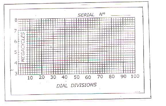
In Italian version it is possible find the drawing of the "
Tuning table" click on word "Tabella" (Table), print and you have
only to complete.
73 de Mario - IK0MOZ
From W1NU
Ciao Mario and Reed: Thanks Mario for latest update. I printed out the
table, very helpful info..Good news on the California and Arizona Paraset
builders. Today I was busy drilling all the holes in the panel and it is
starting to look like the pictures on your website. With my case and panel
finished and all the parts in a box it looks like a Heathkit,hi...I will
build the transmitter part first and get it working while Reed is doing the
RX first. We will keep you informed on our progress Mario and again many
thanks for the Info data #3. Ciao,Ciao de Vic, W1NU
From VE1NU
Looking forward to the additions and suggestions. The hardest part
of the whole project seems to be the 36 H choke. I have been looking at
other regen type radios and have not found any other design that uses
a choke in the plate of the audio amplifier tube.
Thanks for that extra info Mario. Found it and printed it.
Reed
From W1NU
Hello Reed and Mario: Just thought I would give you both an update on my
Paraset progress. I had mounted all components on the panel and then
decided to take them off and paint the panel and letter it with Letra-set
labels before starting to wire the unit. I have been very busy on other
projects associated with the New England Air Museum so I have had to put
the
Paraset project aside for a week. Today I spray painted the panel and the
color I used closely matches the panel on my Wireless Set 18 unit. Reed,
the paint I used is Krylon #1606, Pewter Gray Gloss. I first gave
the panel
a coat of zinc-chromate primer so that the finish coat will adhere better.
I have not painted the case yet and will leave that to last. A few years
ago I bought a box of filter and audio chokes and just found them in my
garage. They are all new in original boxes and one of them is a 30 henry
choke manufactured by Fred Hammond in Canada. The part #157G, is dated
2/20/01 so it is of recent manufacture. The only problem is its size with
mounting centers of 2-7/8" and its 1-1/2" deep x 2-3/8" wide. It has a
resistance of about 600 ohms. I was able to fit it on the panel and I am
going to see how it works out. The only dial I could find is a 1939
National Velvet Vernier with a tuning ratio of 5:1 and its also new
in the
box. My choke is located under the receiver 100 mfd tuning cap and its a
tight fit. I hope I will be able to find room for all the resisters and
capacitors when I go to wire it up, Hi. The panel should be dry be tonight
so that I can apply the lettering tomorrow and hopefully start the wiring
during the weekend. Thanks Reed for the additional info on the Dutch
website and many thanks Mario for all the helpful info on your website. I
will try to get some photos taken by a friend of mine who has a digital
camera and see if my daughter can scan them off to you both. This is a most
interesting project and it all started for me when Reed was looking for a
Cinch-Jones plug and socket. I will keep you both informed on my
progress..73,Ciao,Ciao de Vic, W1NU
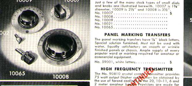
Some dials from a J.Millen catalog
From VE3EDK
Hello:
I have been reading your descriptions of the many Paraset replicas which
have been constructed and I find these projects to be very fascinating.
I have been looking at your No. 2. Drawings for key, coils, impedances and
I would like to know how the coupling of the Tank indicator lamp and the
Aerial tuning indicator lamp is accomplished? I suspect that there is a coupling
coil hidden inside the coil form for the Tank and Aerial tuning coils but
I do not know this for a fact.
How many turns does the coupling coil for each indicator lamp have?
Where is each coupling coil located? This is not visible on the diagram.
Please, what is the diameter in mm for the wire sizes which are used for
winding these coils? In North America we still use the old British system
of wire measurement and I would like to convert metric wire sizes to British
and American sizes.
Tnx es 73,
Ed VE3EDK
From VE3EDK
Hello Mario,
Thank you for the information on the indicator lamp couplings. It's a big
help. We call this method of tuning the tank and antenna "idiot light tuning".
It does not take much intelligence to see that the tuning is correct and
it is highly effective at showing resonance. Thanks for the info.
At this time I am only experimenting with a 1 tube 6V6 transmitter on a breadboard
and I am still assembling parts. The transmitter tuning system is so simple
that I would like to experiment with it before I decide to build a paraset
clone. I just might decide to build the whole unit if my experiment is successful.
Many tnx for the information. I will be watching your site for further developments.
You have a super website. Please keep me informed of developments.
73, VE3EDK
From LA3BI
Dear OM Mario, IK0MOZ
Yesterday I have looked at your home page,
very nice about the Paraset. I already have the description from ON5LJ. We
used this set i Norway during WW2, and I think it is complete impossible to
catch one. If possible, please give some reports to me over the project,
because I want to write about your group in our magazine HALLO HALLO.
73, LA3BI, Erling
From W1NU
Hi Reed and Mario: My computer has been down for about a week and just got
it back today. The Paraset transmitter was finished on February 14 and
after checks across town with Joe, W1GDZ, I heard a chap call CQ on 7111
Khz, where I was testing, and gave him a call. Nice solid QSO resulted with
WE9K in Wisconsin. The Paraset was in its case and it loads beautifully
into my G5RV antenna. Later checks with an antenna matching network in the
feedline and an SWR of 1:1 showed 8 watts output on 40 meters and 7 watts
output on 80 meters. On Tuesday, Feb. 19 I used the Paraset in the WS-19
CW
net and got great reports from the net members on 3703 Khz. All the
components for the receiver are in place and it just needs to be wired up
and I hope to start that this coming week. My HF SB-220 blew up on my
Sunday sked with G4SIA so I have to repair that first--bad week with both
the computer and now my amplifier blowing up, hi..Congrats Reed on getting
the regen part of the Paraset perking away and that gives me some incentive
to get cracking on the wiring of the RX.. I have the key installed also,
its
a miniture key from a Bell System 35C test set and is working well. I have
to get used to keying with my elbow in the air though but I have had a lot
of practice using my GRC-109 rig as it has the key mounted on the top of
the
panel also. Thanks Mario for getting both Reed and I started on this most
interesting piece of gear..A few nights ago on the History Channel on TV
there was a program titled D-Day, The True Story and they showed an agent
in
France using a Paraset and he was keying it with his left hand, hi. By the
way Reed on the TX coil I used two turns of No. 30 wire for the tank and
aerial pickup loops for the lamps. I first installed 2 volt,
60 Ma pilot
lamps and they promptly blew. I then installed 6 volt lamps and they both
lit very bright when the antenna was fully loaded. I have since replaced
them with 28 volt lamps and that seems to be just about right. I did not
want to remove any turns of the coil as they are cemented nicely in place.
You might try a one turn loop for starters Reed. I will keep you informed
on any further progress...73 de Vic, W1NU
Any comment or suggestion will be appreciated