The Paraset
Project
How
to make a replica Norwegian Style.
LA5MT - Asbjørn (Mike) Ursin
During
the year of 2001 i monitored the homepage belonging to IK0MOZ following the
progress of his Paraset project. I
had no intention to build a replica myself in the beginning but I got more and
more interested as Mario & friends struggled to complete their
sets.
The
Paraset was used by SOE and SIS agents in Norway as well as other occupied
countries during WW2. To my
knowledge nobody has made a replica of this radioset in Norway before so why not
be the first one. I started to dig
through various junkboxes looking for components to be used in such a project
and I was very satisfied when I found the gauge for the receiver. This then marked the "official" start of
my Paraset project.
I
visited the Norwegian Resistance Museum in Oslo to have look at an original
Paraset and noticed a couple of details to be included in my replica. In parallel to this I read the book
"Contact" written by Oluf Reed-Olsen (published in 1946) in which he tells his
story as a wireless operator in occupied Norway. His radioset was a Paraset and there was
some really good pictures of the set up he used. Another interesting detail appeared to
be included in my replica - the possibility to connect an external
key.
During
the winter of 2002 I moved my research for components to our Historical Radio
Society of Norway - also located in Oslo.
This is a gold mine for replica builders. Lots and lots of components,
transformers, tubes, variable capacitors etc. By Easter I had in stock all components
needed for the project. The next
problem was to get the zinc to make the chassis and cabinet for the radio. Getting such small quantities is not
easy, but fortunately there was a company that could supply what I needed. I purchased a lot of zinc to be prepared
for perhaps other replica projects to follow this one.
During
the month of may I made the chassis and the metal cabinet for the replica,
drilled all the holes for the major components, made the lettering for all the
controls and in the beginning of June I had all this finished. My aim then was to have an operational
paraset replica by xmas 2002.
Since mostly weekends were available for working on this project the goal
for the completed project seemed to be quite
realistic.
July
is the month of holiday in Norway and then to I had mine. No paraset work for me this
month.
In
August it was the season to visit various fleemarkets and there I came across a
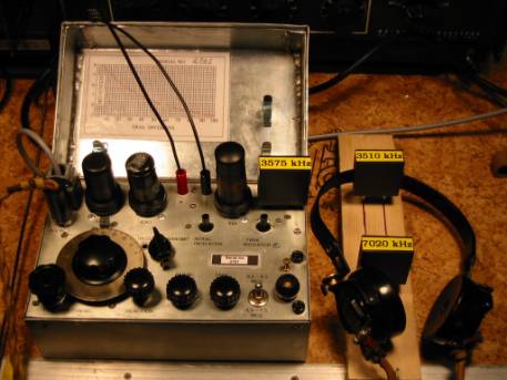
headset that matched my paraset replica perfectly. Further i purchased xtals for the
following frequencies: 3510, 3550,
3575, 3965, 7010 & 7020 kHz.
The xtals were of the HC-6U manufacture and they were to be fit into a
plexiglas block in order to have the same physical size as the original xtals
used during WW2. Further i made a
"replica" of the frequency diagram - showing the link between the reading on the
receiver gauge and frequency - to be installed in the to cover of the paraset
cabinet.
September,
October and November passed
by. No work carried out on the
Paraset replica, but lot of fun doing other things. Though - I made a Mains power supply in
this period. This power supply was
no replica, just an ordinary power supply giving the filament and plate voltage
(6,3V AC and 350V DC). As December arrived and only three weeks to go to
complete the project time became a critical issue. The worst kind of work I know in radio
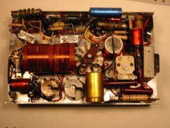
projects is to wind coils. In the
paraset there is one coil for the transmitter and one for the receiver. All together two coils - for me a huge
challenge. I have to admit that
this was one of the reasons for progress being so slow during the autumn. Bu now I had no excuse to postpone this
work. So on the second Sunday in
December this was completed and I was a very relieved man. The transmitter was completed the same
day. By Thursday December 19. At 2135 the receiver was
finished. The Paraset replica was
then complete, but the smoke test had not yet been
done.
On
xmas eve I was quite absent minded thinking only of the smoke test of the
paraset replica scheduled for the following day.

I
started the smoke test by verifying all connections, components and soldering
points. Found two errors: One component was connected wrong and
one soldering was not done at all.
Verification of the power supply was ok. No errors. (I did not verify the interconnecting
cable. This I should have
done).
Then
I connected the mains power cable and switched the mains power on. A red lamp indicator showed the power
was on. No smoke. The filament voltage was 6,6 V with no
load. Ok. The plate power showed
only 270 volts. To low. A bleeder resistor was very hot. Only 10 kohms. To small. Replaced with 62 kohms. The plate voltage then increased to
about 340 V. Ok. Then switch
off. Powersupply
ok.
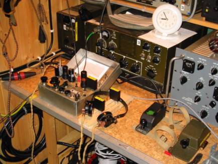
Then
I connected the cable between the power supply and the paraset replica. Antenna and ground wires connected as
well and finally a xtal for the frequency 3575 kHz. The moment when you switch on the power
for the first time is always an exiting moment The red indicator light is put on. No smoke, but not so much else
either. In fact no response at
all.
Damned
. . .
Power
off. My left hand for a brief
moment touches the interconnecting cable.
It was hot !! Something is
wrong. The connectors at both ends
are opened up. There are three
wires - two of them are cross connected.
Given this fairly simple task of connecting three wires was in fact to
difficult for me (hi). The error is
removed. Connectors closed and
cable reconnected. On switch on I
can hear a load audio note in the headset - self oscillation
!!
Damned
. . .
I
switch from receive to transmit. I
have a monitor receiver on the frequency 3575 kHz. I push down the key - and alas - I hear
a beat note in the receiver and there is a light in the anode indicator lamp on
the paraset. I tune the anode
tuning for maximum glow and do the same with the antenna tune. The glow in the antenna indicator lamp
is weak and i find no resonance point.
My "longwire" is 17 meters long and obviously not optimal for this set
up. But the transmitter is
working. I switch off the power,
find the cirquit diagram for the paraset and start studying why there is a self
oscillation. I spend the rest of
the day with this study. I do not
get it. I have made the replica
very close to the original. The
component layout and wiring is very close to the original. The British won the war with such radios
and could not have had such elementary problems with their parasets. Otherwise they would have lost !! There must be something more wrong with
my replica.
The
following day I start examining the receiver an my suspicion is directed towards
a 2uF decoupling capacitor. It is
removed.. When applying power again
the audio note is gone. I now hear
faint noise in the headset. I
connect a signal generator to the antenna input and hear weakly a note in the
headset. Increasing the output from
the generator makes no difference.
I admit that my expectations considering the receiver sensitivity is
modest, but this is to bad. There
still must be something wrong with this radio.
Most
errors in radios can be found by making DC voltage measurements. I find my multimeter and start with the
screen voltage of receiver tube no. 1.
52V !! The normal value
should be 280V. At the plate of the
same tube there is 0V (zero - nothing).
No
plate voltage. I
study the RF choke connected to this plate. Seems like the wire is cut off. Power off. Measuring the conductivity of this RF
choke I get no reading.
Damn
. . .
I
have no spare and I want my paraset replica to work now !! Using a magnifying glass I find two wire
ends in the middle of this RF choke.
I carefully removed the insulation and fix the problem with my soldering
iron. When the power is switched on
again the plate voltage has increased to about 290 V. Ok. Connecting the signal generator again
and now the audio note is roaring out of the headset.
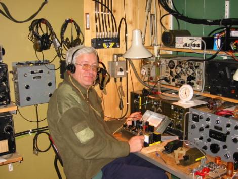
The
signal generator is removed and antenna reconnected to the antenna post. In the headset I can hear noise. Tuning the receiver I hear a lot of
signals. At about 1400 hrs on
December 26. I am ready for my
first qso with this radio. The
receiver is tuned to 3575 kHz. The
transmitter is tuned for max output.
Typically nobody else are qrv at this time. I can copy a lot of cw activity
elsewhere on the 80 meter band, but they are way off 3575 kHz. I tune the receiver around. Sensitivity is remarkably well,
stability is good, selectivity is pore but that is as expected. At 1644 hrs local time suddenly a known
signature on the 80 meter band here in Norway -LA9LE, Tommy - starts calling
CQ. He is calling on 3574 kHz
according to my monitor receiver - a bit to low but I hope he is not using his
narrow cw filter on his receiver.
When he finish I switch my paraset from receive to transmit an I answer
him. Then i switch from transmit to
receive. For a moment I hear only
the noise in the headset - and then - the most beautiful signal a radio ham can
listen to on the band - his own signature: KA LA5MT LA5MT DE LA9LE BT GE MIKE
……. We have a long chat and I get a
quite good report on my signals 589 with a little bit of chirp. I can copy him without any problem in
the paraset receiver. The distance
between us is approx. 150 km.
Hurrah **applauce**clap-clap-clap . . .
success.
The project is then completed. I am a happy owner of an operational paraset replica. In the coming weeks I will spend some time learning to know the performance of this radio. I will have to do some more experiments on the antenna side in order to fine the optimum length of wire. Operating the receiver is a challenge. The frequency range covered is approx. 2.6 - 7-6 MHz. The receiver gauge is divided into 100 divisions giving 40 kHz pr. division. Tuning this to a given frequency is almost impossible. You have to trust that the station you wish to contact has a strong signal. But this is another story.