Thanks to Steve, N5AC for his research and success in determining the mods below! - Jim, N2ZZ
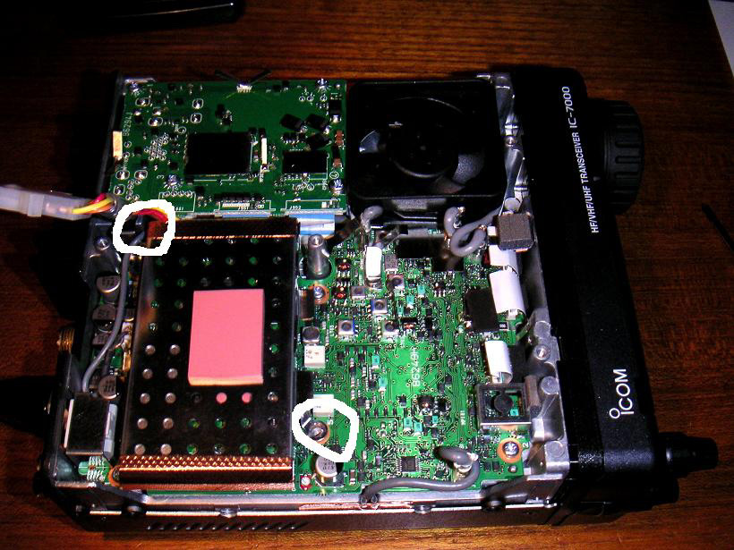 |
Lift off the the top half of the radio case, after removing its securing screws.
Refer to Figure 1. Remove CPU/DSP unit by unscrewing two silver screws holding it down (the silver box on the top of the radio with copper taped sides) and pulling the unit up. (The screws are ringed in white.)
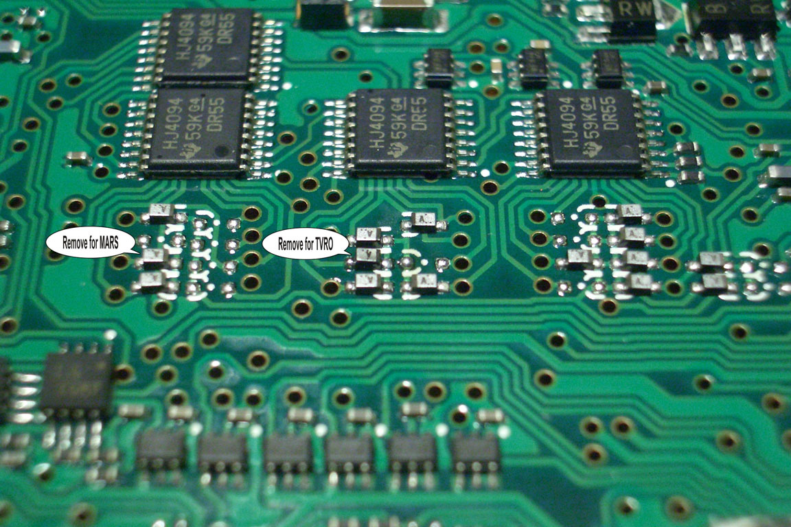
Locate four shift registers and bank of diodes - shift registers are 4094's. There are two next to each other and then a couple more. We'll call the two stacked the "left" ones.
The "middle" shift register if looking from the front of the radio is the target.
Locate bank of SMT diodes (silver with "K" on top on one side) in front of the target shift register. They are in two columns, "left" and "right".
Unsolder one side of the second diode from the front on the left and lift up one side (or remove, slip to the side, whatever you are comfortable with.)
Please observe local traffic laws concerning use of a TV set in a vehicle!
 |
Please refer to the IC-7000 Instruction Manual, Pages 69 - 71.
 |
 |
Here is an out-of-band mod which allows transmitting from 0-54, 118-173 and 400-470 MHz. (Please observe radio regulations!)
Remove CPU/DSP unit by unscrewing two silver screws holding it down (the silver box on the top of the radio with copper taped sides) and pull up. The screws are ringed in white (see Figure 1).
Locate four shift registers and bank of diodes - shift registers are 4094's. There are two next to each other and then a couple more. We'll call the two stacked the "left" ones.
The "left" shift register if looking from the front of the radio is the target.
Locate bank of SMT diodes (silver with "K" on top on one side) in front of the target shift register. They are in two columns, "left" and "right"
Unsolder one side of the second diode from the front on the left and lift up one side (or remove, slip to the side, whatever you are comfortable with.)
Note: After the modification has been performed, the "Band Edge Beep" feature will no longer function, even if it has been enabled.
NOTE: The Automatic Repeater Shift on 2 meters and 440 is not affected by this mod!
Download another TVRO restoral document.
Last updated: 06/25/2007
Copyright © 2005 S. Hicks N5AC and J. F. Boehner N2ZZ. All rights reserved.
Copyright for images reposes with respective authors.
Page created and text edited by A. Farson VA7OJ/AB4OJ.