
Transverter per 24 GHz (2016)
Transverter for 24 GHz (2016)
|
|
photo gallery
![]() Cliccare sulla foto per vedere la massima grandezza con
la miglior qualità
Cliccare sulla foto per vedere la massima grandezza con
la miglior qualità
![]() Click
on a picture to view it full size with full quality
Click
on a picture to view it full size with full quality
|
|
|
|
|
|
|
|
|
|
|
|
![]()
![]() Transverter per 24 GHz (2016)
Transverter per 24 GHz (2016)
![]()
Quando iniziai ad appassionarmi di microonde era l’anno 1996. Il tutto
cominciò con la costruzione di un RTX per trasmissione packet in banda 23 cm.
Il mio primo QSO in banda 23 cm avvenne il primo dicembre 1996 appunto in
packet. Negli anni a venire passai alla costruzione di rtx e transverter fino a
10 GHz.
A questo punto dicevo a me stesso ‘qui finisce la mia avventura in microonde e
mai passerò ai 24 GHz’.
Però ‘mai dire mai’ e al mercatino di Moncalvo di settembre 2014 io e Beppe
I1GPE acquistammo
due parabole ANDREW (una da 60 cm. per me ed una da 30 cm. per Beppe) complete
di illuminatore con uscita in guida d' onda adatte per i 24 GHz. Da quel
momento iniziò la nostra grande avventura per la costruzione di un transverter
per la banda dei 24 GHz.
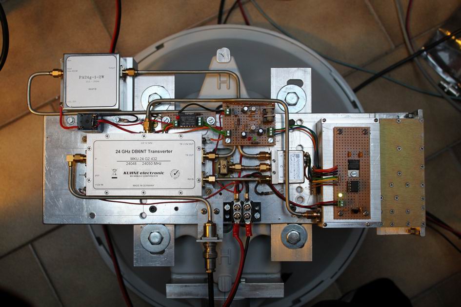
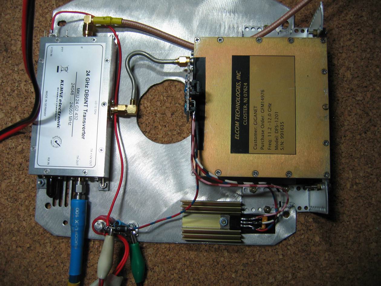
Il transverter è composto da diversi dispositivi collegati tra di loro che sono:
1 – transverter DB6NT modello MKU 24G2-432
2 – oscillatore locale con il modulo Elcom DFS 1201
3 – schedina per cambio frequenza sul modulo Elcom DFS 1201
4 – PA da 2 watt by DG0VE
5 – relè coassiale Ducommun modello 2SE1T11JB
6 – schedina di pilotaggio per relè coassiale
7 – sequencer
![]()
La scelta del transverter senza ombra di dubbio è caduta
sul DB6NT modello MKU 24G2-432.
Esso è equipaggiato di 4 connettori SMA: TX out, RX in, LO 12GHz e IF.
Come tutti i transverter DB6NT il PTT si può attivare tramite un piedino
presente (PTT) oppure tramite un tensione di 8…12 V sul centrale del cavo
coassiale: io ho scelto questa ultima opzione per evitare di aggiungere un
ulteriore filo!
La potenza di uscita di questo transverter in 24 GHz è di circa 30 mW.
![]()
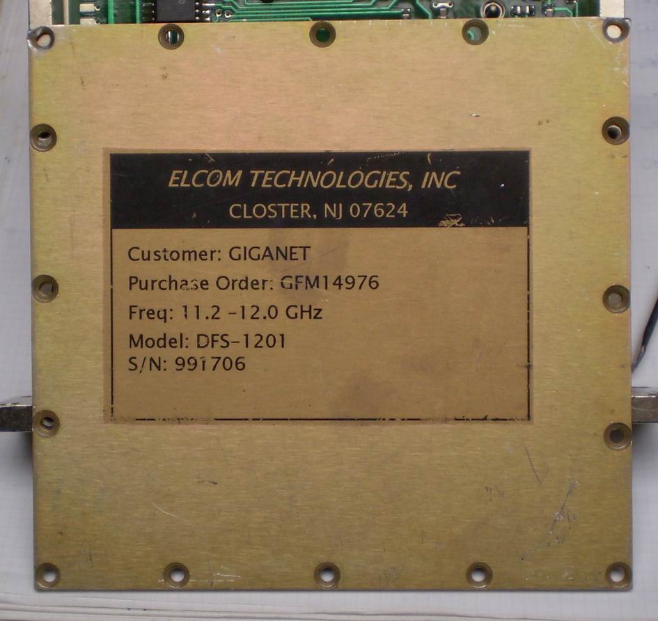 Documentandoci sul web scoprimmo che qualcuno usò per l’oscillatore locale il
modulo DFS 1201 della Elcom che, opportunamente modificato, poteva essere
utilizzato allo scopo. Il costo si aggirava sulla quarantina di Euro. Dopo circa un
mese il modulo arrivò a casa pronto per essere modificato.
Documentandoci sul web scoprimmo che qualcuno usò per l’oscillatore locale il
modulo DFS 1201 della Elcom che, opportunamente modificato, poteva essere
utilizzato allo scopo. Il costo si aggirava sulla quarantina di Euro. Dopo circa un
mese il modulo arrivò a casa pronto per essere modificato.
È un oscillatore
apparso sul mercato del surplus qualche anno fa, che copre la gamma da 11.2 a 12 GHz. Cercando su internet si trova molta documentazione e modifiche da parte di
molti OM che lo hanno utilizzato come oscillatore locale per un transverter a 24
GHz. Molto utile è stata la descrizione di Roberto IZ4BEH pubblicata sulle sue
pagine web (
http://www.iz4beh.net/OL_FSL.html ).
È necessario costruire una piccola
schedina con un PIC da innestare nel connettore del modulo con lo scopo di riprogrammare l’oscillatore con la frequenza utile per i nostri
bisogni. Noi
abbiamo scelto un IF di 432 MHz per il nostro transverter e i calcoli di
programmazione devono quindi essere basati su questa frequenza.
Il problema è
che, per come è stato progettato il DFS 1201, non possiamo programmarlo come vogliamo
ma bensì solo a salti di 3 MHz. con una frequenza finale che purtroppo non cade
a "zero kilohertz" ma ad un valore random.
Mi spiego meglio con un esempio: un segnale a 24048.100 MHz non lo riceveremo a 435.100 MHz ma bensì a 434.833 MHz.
Sempre per lo stesso problema
Comunque ritengo che
questo non sia un grosso problema anche perché i QSO sui 24 GHz si fanno
esclusivamente su sked per cui è sufficiente prendere accordi per esempio sempre
a 24048.100 MHz (come nel 99% dei casi avviene). Se poi abbiamo la fortuna di
ascoltare qualche beacon ci faremo una tabella con le frequenze convertite.
In ogni
caso, il DFS 1201 dopo pochi minuti dall' accensione e' fermo in frequenza e
permette QSO con totale stabilità di frequenza
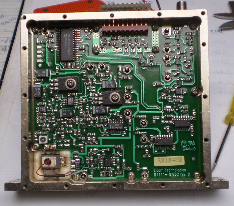
come si presenta l'interno del modulo DFS 1201
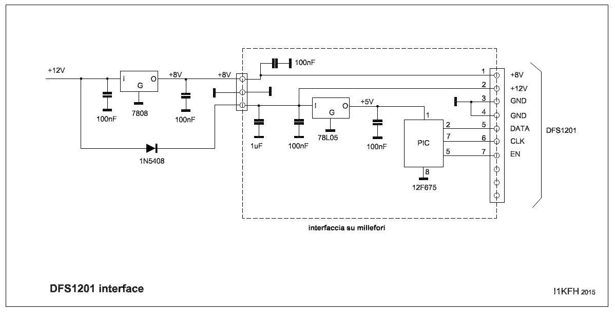
Costruzione della schedina di programmazione della frequenza.
Abbiamo utilizzato allo scopo una piccola piastrina millefori dove viene
alloggiato il PIC 12F675 (su zoccolo), un regolatore di tensione 78L05 e qualche
condensatore.
È necessario utilizzare un connettore maschio direttamente saldato sulla
piastrina per l’innesto al modulo DFS 1201.
Le dimensioni della piastrina devono essere ridotte al minimo necessario per non
sprecare spazio.
Il regolatore di tensione 78L05 (sulla piastrina) serve per alimentare il PIC
12F675. Il modulo Elcom ha bisogno di due tensioni per il suo funzionamento:+8V
(120mA) e +12V (260mA). Un 7808 su di una piccola aletta di raffreddamento
(esterno alla schedina) fornisce il +8V al DFS 1201.
Il +12V viene fornito dall’alimentazione generale del transverter. Se questa
alimentazione fosse maggiore (nel mio caso 13.8V) è meglio inserire in serie un
diodo per abbassare di un volt circa questa tensione. Io ho usato un diodo
1N5408 solo perché ne avevo a disposizione.
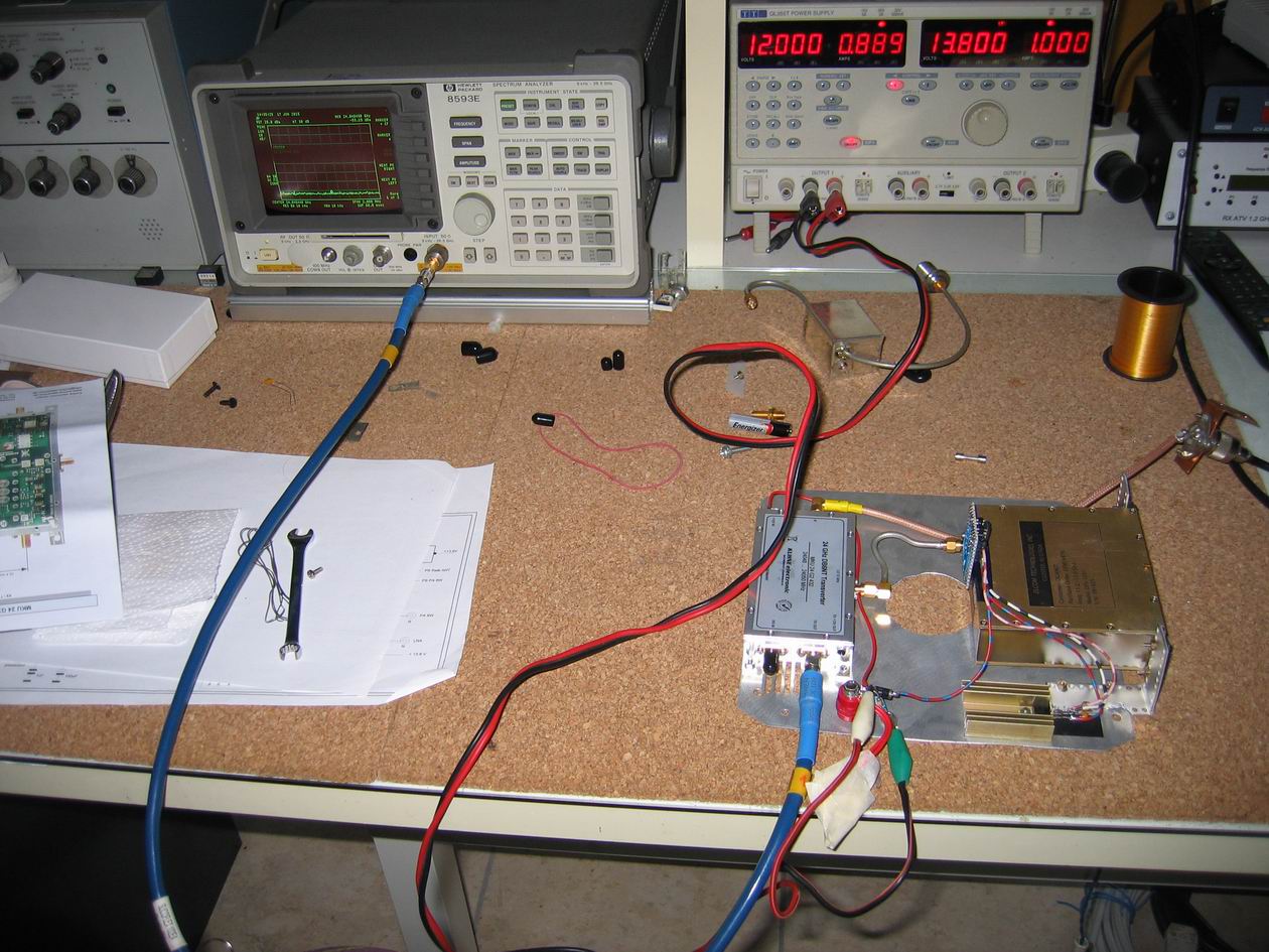
Una volta cablata la schedina e programmato il PIC per la frequenza scelta
dell’oscillatore locale la innesteremo nel connettore del modulo Elcom.
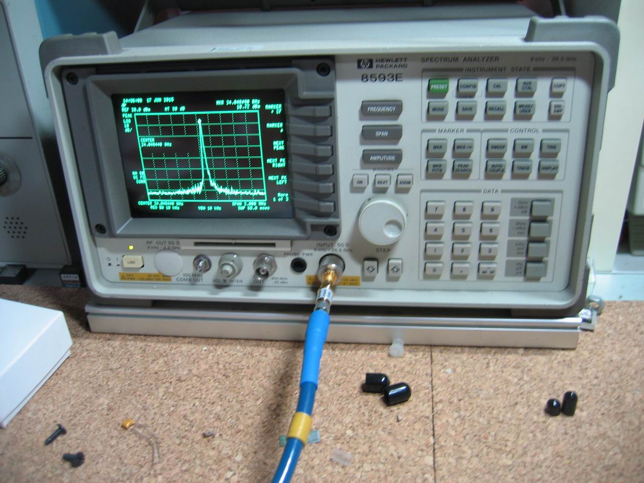
Collegare a questo punto l’analizzatore di spettro in uscita al modulo DFS 1201,
dare tensione e, dopo 3-4 secondi, dovrebbe apparire il picco sulla frequenza
programmata.
![]()
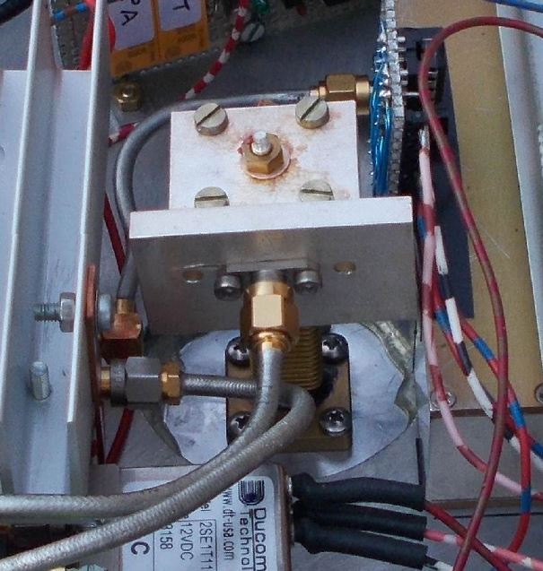
Non è una scelta facile perché deve essere adatto per una
frequenza di almeno 24 GHz.
Per questioni di costo abbiamo acquistato dagli Stati Uniti su Ebay un paio di
relè Ducommun modello 2SE1T11JB, con bobina a 12 V e un range di frequenza dalla
DC a 26.5 GHz.
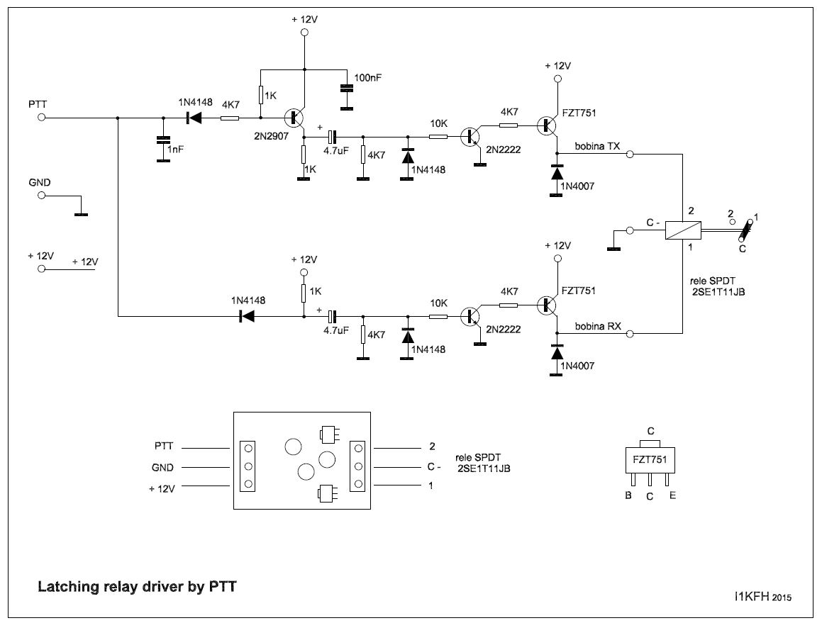
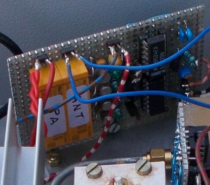
Sono relè coassiali a basso costo che però necessitano di un circuito
particolare di pilotaggio perché sono ‘latching’ o bistabili. Lo schema di
questo circuito è stato scelto tra i tanti trovati sul web e poi modificato per
il nostro uso.
Nel mio caso lo spazio a disposizione nel contenitore del transverter è
veramente poco per cui ho deciso di usare componenti SMD per ridurne le
dimensioni. Come si può vedere dallo schema per pilotare le due bobine del relè
coassiale ho usato un driver SMD FZT751 recuperato da una vecchia scheda da
rottamare. In ogni caso non è un componente critico, l’importante è che abbia
una corrente sufficiente per il pilotaggio della bobina del relè.
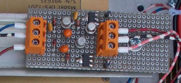
i componenti SMD si trovano nella parte inferiore
![]()
Il PA è stato acquistato da DG0VE che, a parità di
prezzo-prestazioni, secondo noi era il migliore.
Facendo
riferimento alle caratteristiche
descritte sul manuale con 40 mW input (massimo pilotaggio ammesso) si hanno 2 W in
uscita. Il dispositivo necessita di una bella aletta di raffreddamento.
È previsto un piedino con una tensione di ‘monitor’ proporzionale alla potenza
di uscita che ho portato in stazione per avere un controllo visivo, tramite uno
strumento analogico, del buon funzionamento del sistema.
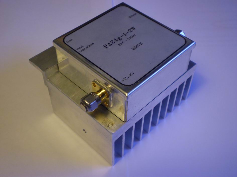
PA con aletta di raffreddamento (by I1GPE)
![]()
Il sequencer è sempre lo stesso usato in molte altre
occasioni.
Sempre per ridurre gli spazi è stato cablato su una piastrina millefori e
utilizzando il più possibile componenti SMD.
![]() La parabola
La parabola
La parabola con illuminatore sono stati acquistati al
mercatino di Moncalvo per puro caso, dando il via alla corsa dei 24 GHz.
L’attacco per l’illuminatore è in guida d’onda, per cui è stato necessario
procurarsi degli adattatori guida d’onda-connettore SMA.
adattatori
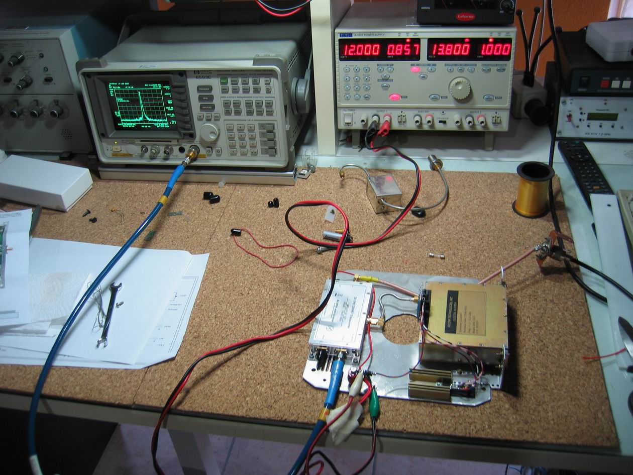
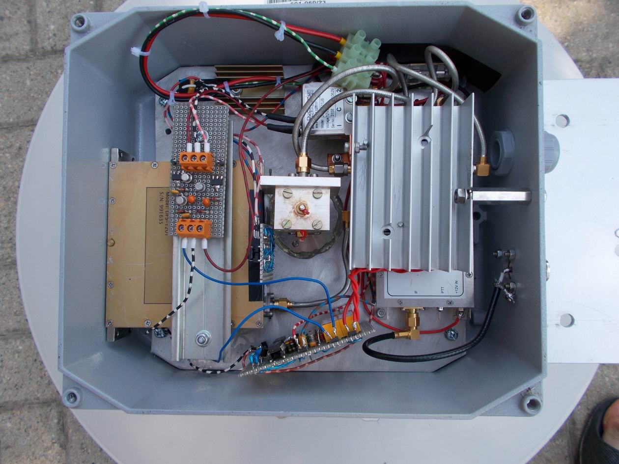
![]() Cablaggio del transverter
Cablaggio del transverter
Il cablaggio per un transverter a 24 GHz è molto difficile,
è da curare tutto nei minimi particolari, basta una minima disattenzione per
cadere in un insuccesso totale.
Il mio transverter è stato installato sul tetto collegato direttamente alla
parabola per cui è molto importante tenere conto delle condizioni atmosferiche
sia estive che invernali.
A questo punto inizia anche un fine lavoro di meccanica per cercare di fare
quadrare tutto in poco spazio. Io ho usato un contenitore di alluminio a tenuta
stagna e siliconando eventuali ipotetiche fessure tra contenitore e parabola,
che, alla fine diventano un blocco unico.
Dalla parte inferiore del contenitore di alluminio ho praticato un foro per un
passacavo e un altro per un connettore N femmina per l’IF. Nel passacavo avremo
un cavo con tre fili: due per l’alimentazione di adeguata sezione e uno di
‘monitor’ dal PA. Al connettore N collegheremo un cavo RG213 che porteremo in
stazione alla nostra IF a 435 MHz.
Dovremo poi alloggiare tutti i moduli cercando una sistemazione strategica per
il collegamento tra di loro che va fatto tramite cavetti intestati SMA
maschio-maschio.
Non tutti i cavetti vanno bene, esistono anche quelli apposta per le frequenza
dei 24 GHz, l’ideale sarebbe poi costruirseli della lunghezza giusta per avere
una minor perdita di segnale.
È un attimo perdere 3dB su un cavetto , e 3 dB sono potenza dimezzata e segnale
di ricezione dimezzato.
Io ho cercato di selezionare i migliori tra quelli che avevo provandoli con
l’analizzatore di spettro. Tanto per fare un esempio all’uscita del mio
transverter mi trovo con circa 0.5 W al posto dei 2 W teorici, però di meglio
non sono riuscito ad ottenere.
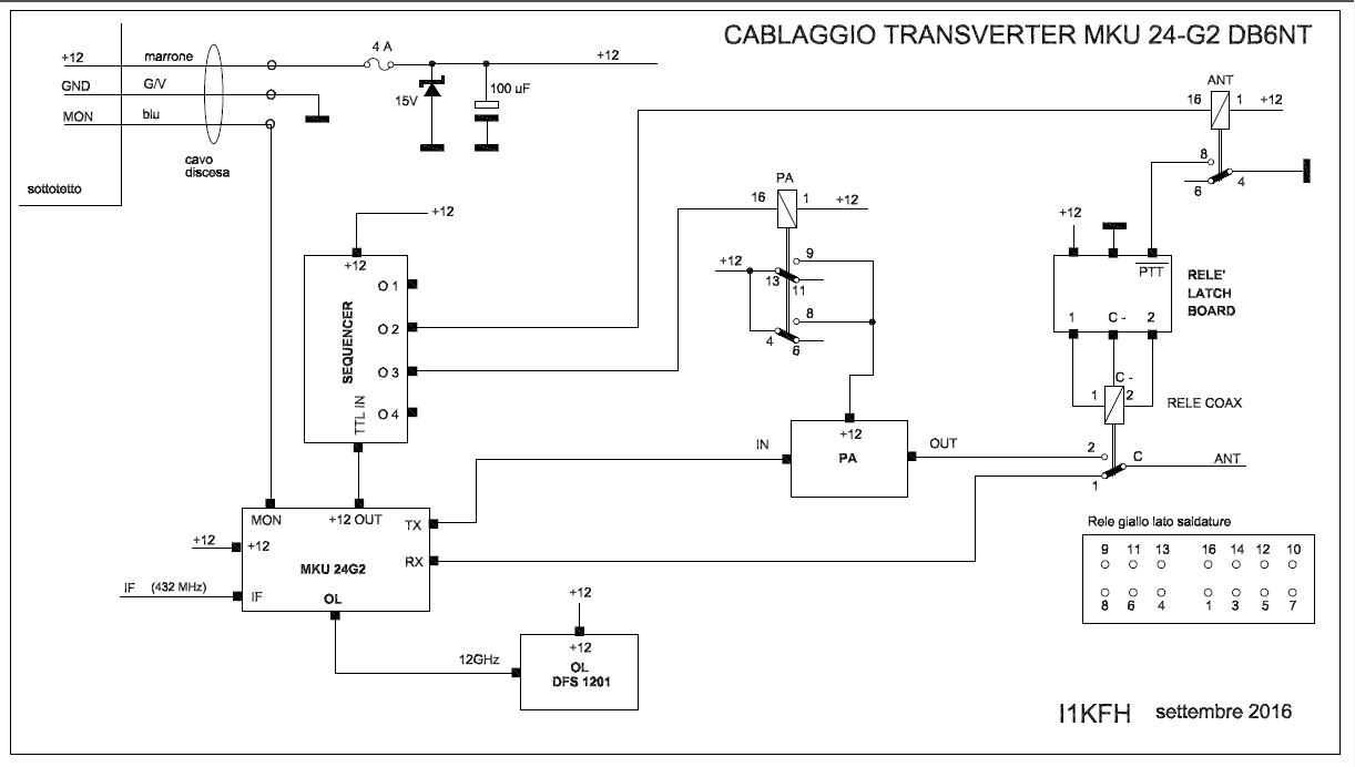
Disegno del Cablaggio del Transverter completo
![]() Primo QSO in 24 GHz con Giampiero IW1CKM
(14 Km)
Primo QSO in 24 GHz con Giampiero IW1CKM
(14 Km)
https://www.youtube.com/watch?v=MAQdzgdRp8s
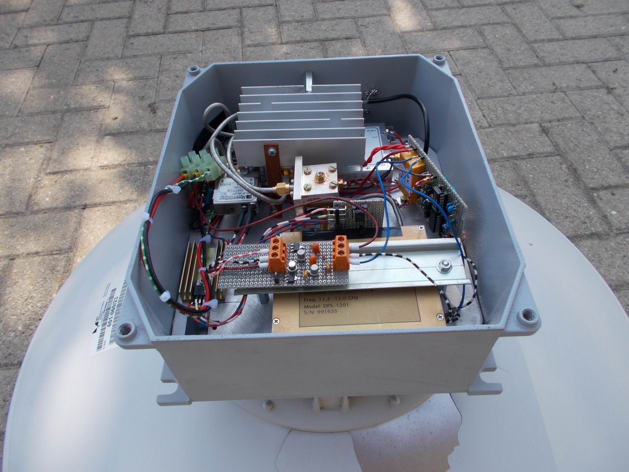
![]() Transverter assemblato da I1GPE
Transverter assemblato da I1GPE
![]()
![]() Transverter for 24 GHz (2016)
Transverter for 24 GHz (2016)
![]()
When I
started to get interested in microwave it was the year 1996. All this began with
the construction of an RTX for packet transmission in the 23 cm band.
My first QSO in the band 23 cm occurred December 1, 1996 in packet. In the
coming years I spent in the construction of RTX and transverter up to 10 GHz.
At this point I said to myself 'here ends my adventure in microwave and never
will pass the 24 GHz'.
But 'never say never' and the market in Moncalvo of September 2014 I and Beppe
I1GPE purchased two ANDREW parables (one 60 cm. for me and one 30 cm. for Beppe)
complete with illuminator with exit guide d 'suitable wave for 24 GHz. From that
moment he began our great adventure for the construction of a transverter for
the 24 GHz band.
The transverter is made up of several devices which are :
1 - DB6NT transverter MKU 24G2-432
2 - local oscillator with Elcom form DFS 1201
3 - board for exchange rate on the DFS module Elcom 1201
4 - 2 watt PA by DG0VE
5 - Coaxial relay Ducommun model 2SE1T11JB
6 - piloting board for coaxial relay
7 - sequencer
![]()
We decided
to use the DB6NT type MKU 24G2-432.
It is equipped with 4 connectors SMA: Out TX, RX, and IF LO 12GHz.
Like all DB6NT transverter the PTT can be activated by pin on box (PTT) or by
voltage (8 ... 12 V) on the center of the coaxial cable: I chose this last
option to avoid adding an extra wire!
The output power of this transverter at 24 GHz is approximately 30 mW.
![]()
It is an oscillator appeared on the surplus market a few years ago, which covers
from 11.2 to 12 GHz range. Searching the internet is a lot of documentation and
changes by many OM who have used it as a local oscillator for a transverter to
24 GHz.
Very good was the Robert IZ4BEH description published on its web pages
It is necessary to build a small board with a PIC and next connect it in the
module connector with the new program and with the new frequency. We have chosen
a 432 MHz IF for our transverter and programming calculations must be based on
this rate.
The problem is that, as it was designed for the DFS 1201, we cannot program it
as we want, but rather only in jumps of 3 MHz. With a final rate which
unfortunately does not fall to "zero kilohertz" but to a random value.
For example: a signal on 24048.100 MHz we not receive to 435.100 MHz but
434.833 MHz.
For the same problem we had to choose between an IF 428 or 435 MHz. Our choice
fell on 435 MHz.
I still think that this is not a big problem because the QSO on 24 GHz are made
exclusively on sked and many time at 24048,100 MHz . If we have the good fortune
to hear some beacons we'll have a table with the converted frequencies.
In any case the DFS 1201, after a few minutes next power up, is possible a QSO
with total frequency stability.
the inside of the DFS 1201 module
Construction of the frequency programming board.
We used a
small plate breadboard where is located the PIC 12F675 (on the socket), a
voltage regulator 78L05 and some capacitor.
You must use a male connector soldered directly on the board for connection to
the DFS 1201 module.
The size of the board should be kept to the minimum necessary because the space
is very important.
The PIC 12F675 is supplied by a voltage regulator 78L05 (on the board). The
Elcom module needs two voltages for its operation: + 8V (120mA) and + 12V
(260mA). A 7808 on a small cooling fin (external to the board) provides the + 8V
to the DFS 1201.
The + 12V is supplied from the main transverter. If this power is greater (in my
case 13.8V) it is better to put a diode in series to lower one volt about this
tension. I used a 1N5408 diode just because they had available.
Once wired the board and programmed the PIC for the new local oscillator
frequency insert the board into Elcom module connector.
Connect at this point the spectrum analyzer output to DFS 1201 module, supply
voltage, and after 3-4 seconds, it should see the peak on the programmed
frequency.
![]()
It is not an easy
choice because it must be suitable for a 24 GHz frequency.
For reasons of cost we purchased from the United States on Ebay two relay
Ducommun 2SE1T11JB model, with a 12 V coil and a frequency range from DC to 26.5
GHz.
These coaxial relays are low-cost but require a particular driving circuit
because they are 'latching' or bistable. The scheme of this circuit has been
chosen the web and then modified for our use.
In my case the space available in the box of the transverter is very little so I
decided to use SMD components to reduce its size. As you can see from the
diagram to drive the two coils of the coaxial relay I used a SMD FZT751 driver
recovered from an old card. In any case it is not a critical component, the
important thing is that a sufficiently high current for the driving the relay
coil.
Wiring Diagram of relay command
mounted circuit on breadboard
![]()
The PA was purchased
by DG0VE that, with 40 mW input (maximum permissible driving) you have 2 W
output. The device requires a good cooling fin.
There is a pin with a 'monitor voltage' proportional to the output power that I
brought to the station to have a visual control, using an analog instrument, the
proper functioning of the system.
PA with cooling fin (by I1GPE)
![]()
The sequencer is
always the same one used on many other occasions. (See description)
Always to reduce the spaces has been wired on a small plate breadboard, and
using the most possible SMD components.
mounted circuit on breadboard
![]() The dish
The dish
The dish with
illuminator were purchased at Moncalvo flow market .
The attack for the illuminator is in the waveguide, for which it was necessary
to procure the adapters waveguide-SMA connector.
wave-guide SMA connector adapters
![]() Transverter wiring
Transverter wiring
The cabling
for a transverter to 24 GHz is very difficult, is to treat everything in detail,
just a minimal inattention to fall into a total failure.
My transverter has been installed on the roof connected directly to the dish so
it is very important to take into account the weather conditions both summer and
winter.
At this point it also begins a mechanical work for installing everything in a
small space in an aluminum box.
From the lower part of the aluminum box I drilled a hole for a cable entry and
another for an N female connector for the IF. In the cable guide we will have a
cable with three wires: two for the supply of adequate section and a 'monitor'
from the PA. The N connector will connect a RG213 cable that will bring the
station to our IF to 435 MHz.
Then we will have to stay all modules looking for a strategic arrangement for
the connection between them by SMA male-male cables.
Not all cables are good, there are also for the frequency of 24 GHz, the ideal
would then make it to the right length to have a lower loss of signal.
It is a moment to lose 3dB on a cable, and 3 dB is half power and half reception
signal.
I have tried to select the best among those that had the trial of a spectrum
analyzer. As just one example, the output of my transverter is about 0.5 W
instead of 2 W from manual.
Wiring Diagram of the complete Transverter
![]()
https://www.youtube.com/watch?v=MAQdzgdRp8s
![]() Transverter assembled by I1GPE
Transverter assembled by I1GPE
|
|

