Hi, I am Tony I0JX
A electronic travel
in the eastern world...
AN AMPLIFIER FOR 6 & 160
METERS
(ALSO WORKING ON 15, 12 AND 10 METERS)
Until recently, my experience with russian electronic equipment was limited to high-voltage ceramic capacitors and some other components. Generally speaking, I have hardly been attracted by the appearance of russian equipment; they often utilize an "hammered" gray varnish which cannot compare with silver-plated or anodized panels common in US-made equipment.
Despite my instinctive coldness with regard to russian stuff, I have been tempted to buy a surplus russian power amplifier which I have seen on sale for years at the Friedrichshafen hamfest (there were several units around, so perhaps they should still be available). I was mainly attracted by the external-anode tube (a GU-43B tetrode) and its nice ceramic socket, by the big motor-driven tank rotary coil and by the fact that it was evidently a VHF power amplifier appearing very suitable for the 50-MHz band, my favorite one! AND MOST OF ALL BECAUSE IT WAS A GOOD OCCASION TO PLAY WITH ELECTRONICS...
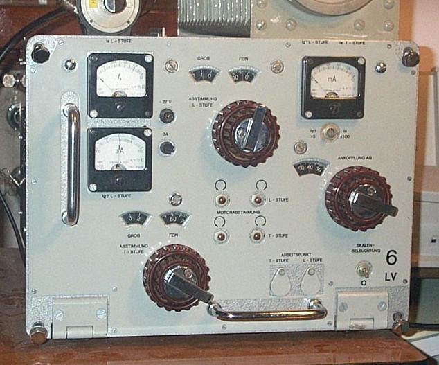
To make a long story short, at the 1999 hamfest I decided to buy one unit which was in almost perfect conditions and brought it back home (with two new spare tubes). You see here how the front panel looks like (after removing those ugly meter shields).
After a brief inspection I determined the following:
On the front panel you can read the marking "6 LV". At this regard please note:
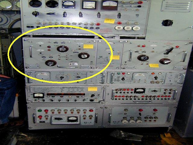
Below you can the see the R-137 station (with the 20 MHz - 60 MHz 6 LV amplifier in the yellow ellipse)
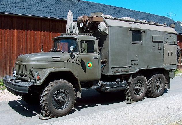
and here you can see the ZIL-131 truck.
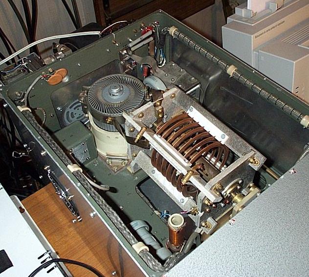
Let us now give a look to the interior. This picture was taken before the modification I made for having it to operate also on 160 meters).
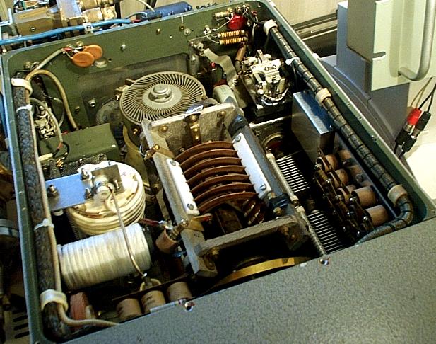
This is after the modification.
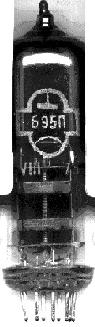
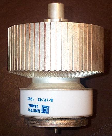
The original glass-metal GU-43B tube can be directly replaced by a ceramic-metal version named Q-1P/42. This tube, made in Poland by LAMINA and distributed by UNITRA, is much nicer than the GU-43B, also because it is fully silver plated, see picture below.
As the 6 LV only was a part of a transmit station, it was not designed as a stand-alone amplifier. In practice, the work I had to do to make the 6 LV working can so be summarized:
With regard to the GU-43B plate voltage, I took the HV from the power supply of my Henry 4K-Ultra amplifier, which can deliver either 3,000 or 4,000 VDC at currents well in excess of 1A, with exceptionally good stabilization (resonant choke power supply).
- -27 VDC, 1.5A, for relays and motors;
- 6.3 VAC, 1.5 A, for the driver stage filament;
- +225 VDC, 100 mA, for the driver stage plates;
- 12.6 VAC, 7A, for the GU-43B filament;
- -120 VDC, 50 mA stabilized, for the GU-43B grid bias;
- +400 or +450 VDC, 120 mA stabilized, for the GU-43B screen;
The grid bias shall actually be adjustable around -80 V; at -120 V the tube stays well interdict.
Now my experience. The first problem I had was an internal discharge within the GU-43B (plate to screen) when the plate voltage was raised above about 2000 V. After consultation with some russian experts, I learnt that such behavior is normal for russian tubes having not been used for long periods, and that a start-up procedure is required. There are several versions of such procedure; I tried that of keeping the tube for some 48 hours with half the filament voltage (and no other voltages), and gradually raising the voltage, during the subsequent 24 hours, until nominal. Miracle: the problem did no longer show up and for the first time I could see an idling current which I adjusted to some 200 mA (a value which I thought to be reasonable).
Another problem was that the red 15nF screen by-pass capacitors embedded within the GU-43B socket went incredibly short one after the other. I had to replace all 16, and replaced with disc-type capacitors.
After curing those problems, the amplifier immediately started to work fine, with no minimal signs of oscillation despite its gain of some 40 dB (a drive power of less than 200 mW is required, in virtue of the driver stage!). To obtain such a low RF drive, I terminate the 100-W exciter on a dummy load through a -25dB coupler which provides the drive signal. I normally increase drive power until I see no little grid current.
The tube data sheet states that maximum plate current is 1 A. In practice you can easily drive the tube up to more than 1.2 A, with zero grid current (pure class AB1). The maximum screen dissipation is 28 W, this meaning that, at 400 V, the average screen current should not exceed some 70 mA, but peaks up to 100 mA or even more are tolerated.
I have tried operating the amplifier at 4000 V despite, according to the tube sheet, the plate voltage should not be raised above 3300 V. I also tried using a screen voltage of 450 V, a value still within the tube specifications (500 V max.). The amplifier works fine under all such conditions, no apparent problem.
Let's now discuss some issues concerning the power supply which requires some care, mainly because of the stabilization requirement and the need for protection circuitry. I will not here address the plate supply, for which you can find several solutions in the Radio Amateur's Handbook; a well designed input choke power supply (or a resonant choke one)is recommended, also to keep voltage minimum under no-load conditions.
The following aspects shall be taken into account for power supply design:
In practice, to avoid all problems, the power supply shall incorporate a protection circuitry designed according to the following logic:
|
|
Filament
voltage |
Grid |
Screen
voltage |
Plate
voltage |
Transmit
relay |
|
If
120s have not yet elapsed since filament was powered |
n.a. |
must
be present |
(*) |
(*) |
keep
disabled |
|
If
filament voltage disappears |
n.a. |
leave
present |
(*) |
(*) |
disable |
|
If
grid bias disappears |
leave
present |
n.a. |
remove |
remove |
disable |
|
If
screen voltage disappears |
leave
present |
leave
present |
n.a. |
leave
present |
disable |
|
If
screen current exceeds 150 mA |
leave
present |
leave
present |
remove |
leave
present |
disable |
|
If
plate voltage disappears |
leave
present |
leave
present |
remove |
n.a. |
disable |
(*) there is not a wide consensus on whether plate or screen voltage may be applied before the cathode has fully warmed up (having assumed that the tube is anyway kept interdict by an appropriate grid bias).
The schematic diagram of my grid bias supply is shown below.

The three zener diodes shall be mounted on an heat sink. The transmit relay is operated simultaneously with the antenna relay. Grid bias so varies from -120 V (RX mode) to an adjustable value around -80 V (TX mode).
The schematic diagram of my screen supply is shown below; the design is such that occasional plate-to-screen discharges do not (normally) cause power transistors failures. Output voltage is either 400 V (LO) or 450 V (HI).
The resistor marked "R" shall have a low value (in the order of 10 ohm); its purpose is to generate a voltage proportional to the screen current. The resistor will act as a sensor for the screen overcurrent protection circuitry (and also as a shunt for the screen current meter if you wish). A switch removing the screen voltage by disconnecting the negative side of the supply from ground is also shown; this switch shall be controlled by the protection circuitry.
The two BU208A transistors shown at top shall be mounted on a suitable heat sink. You may well use zener diodes in place of the gas regulators (OA2, OB2), but, after destroying several set of diodes, I concluded that using regulators is a more cost-effective solution.
NOW...
Recently I told myself: why should the amplifier only work on 50 MHz? My Henry linear 4K-ultra operates neither on 50 MHz nor on 1.8 MHz, so why not having the russian amplifier to also work on 1.8 MHz? On the other hand the sunspot cycle peak is shortly going on the low side. Profiting of the great frequency difference, a relatively simple solution should be possible, I thought.
After some brainstorming, I firstly modified the input circuit. For 1.8 MHz operation, the tube grid is disconnected from the 50-MHz driver stage, and directly connected to a 50-ohm 100-W resistor constituting the RF load for the exciter. In this way the amplifier has two separate inputs, one for 50 MHz and the other one for 1.8 MHz.
The grid capacitance of the GU-43B ranges 80 - 100 pF, this introducing a parallel reactance of some 1,000 ohm at 1.8 MHz. Such an high value does not cause noticeable input SWR; anyway you may resonate it if you so wish (by means of a suitable coil in parallel to the 50 ohm resistor).
The main issue was the output pi-network, as I had no intention to modify the existing 50-MHz circuitry which works very fine. Behind the front panel, there is a very complex mechanical system (motors, gears, etc.), this fact preventing the possibility to add anything on the front panel.
To explain the solution I adopted, let us consider the original 50-MHz pi-network design.
The (measured) 29 pF plate capacitor does not exist in reality, it actually being constituted by the tube plate capacity and stray capacitance. Tuning is obtained by turning the rotary coil which is at HV potential, the 500-pF isolation capacitor being placed after the coil itself. I believe that this solution was adopted because, for operation on a wide frequency range, it significantly simplifies the RF choke design, this being connected at a low-impedance point.
To add 1.8-MHz capability, I had an idea that required removing the short between the sliding contact and one end of the rotary coil (see diagram above). But removing that short develops a very high RF voltage at the free end of the coil (at 50 MHz), with consequent arcing. As a compromise, I replaced the original short with a 100 pF arc-quenching capacitor, as shown below.
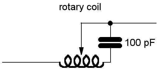
This capacitor is nearly a short at 50 MHz. The resonant frequency of the parallel circuit is always much higher than 1.8 MHz, so the added capacity has a negligible effect on that band. After installing the capacitor, I noticed no change at all with regard to 50-MHz operation.
Then I added some components, those shown in red.
There is no change at all for the 50-MHz pi-network. The 50-MHz RF choke has instead been rebuilt such as to handle higher RF current, it now forming integral part of the 1.8-MHz tank coil. No-50 MHz energy can reach the 1.8-MHz RF output, also thanks to the 1.8-MHz antenna tune capacitors shorting any residual 50 MHz signal to ground.
Band switching is very simple: at 1.8 MHz, a ceramic relay grounds the 50-MHz RF output, thus preventing 1.8-MHz energy from reaching that output. Besides, the 500-pF capacitor gets so grounded, it de-facto becoming the plate capacitor for the 1.8-MHz pi-network (it can be demonstrated that the left-hand side part of the rotary coil has a negligible effect at 1.8 MHz, and can then be disregarded for all practical purposes).
As the 100 pF capacitor also has a negligible effect at 1.8 MHz, the right-hand side part of the rotary coil can be considered to be in series with the 1.8 MHz fixed tank coil (which includes the 50-MHz RF choke), this fact permitting to tune the pi-network by turning the rotary coil, just like for 50 MHz.
After the 8000-pF insulating capacitor, you'll see the 1.8-MHz antenna tune capacitor, consisting of a fixed capacitor in parallel with a 600-pF variable capacitor permitting to vary the loading across the relatively small frequency range (1.825 - 1.850 MHz). The fixed capacitor actually consists of a bank of capacitors in parallel, for a total capacity of 1800 pF. Should a lower capacity be actually needed, depending on the actual antenna impedance, one can easily disconnect some of the capacitors.
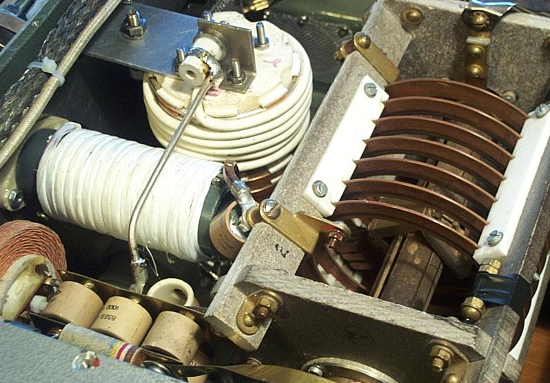
Picture below shows, besides the rotary coil, some of the added components for 1.8-MHz operation, namely an E. F. Johnson 600 pf (300+ 300) antenna-tune variable capacitor mechanically ganged to the original 50-MHz antenna-tune variable capacitor, eighteen 100-pF fixed capacitors (Centralab Series-50) in parallel to the variable one, and the ceramic relay (on the left hand side) shorting the 50-MHz antenna-tune capacitor .
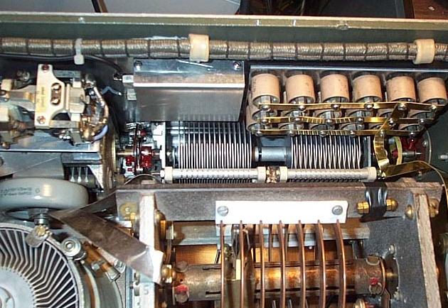
On the other side of the rotary coil there are the rebuilt 50-MHz RF choke, the added 1.8-MHz tank coil, the 100 pF arc-quenching capacitor (Centralab Series-50) and the 8000-pF insulation capacitor, actually consisting of eight 1000-pF capacitors (Centralab Series-58) in parallel. These are shown in picture below.
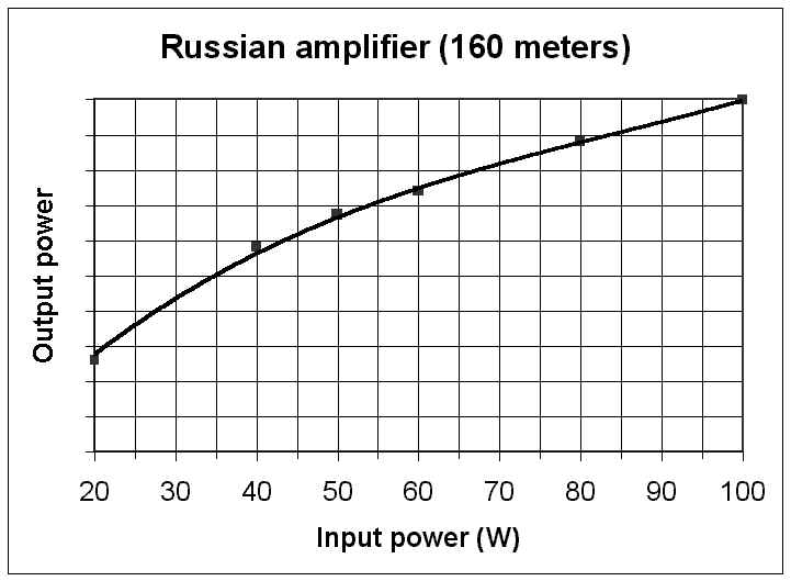
The amplifier performs very well; its efficiency gets close to 70%. Look at the measured input / output power response. Just 100 W RF are needed to obtain maximum output power (at 1.3 A plate current).
Return to the I0JX home page