Hi, I am Tony I0JX
The Navy RBZ receiver
[Historical data on RBZ courtesy of Dennis Starks]
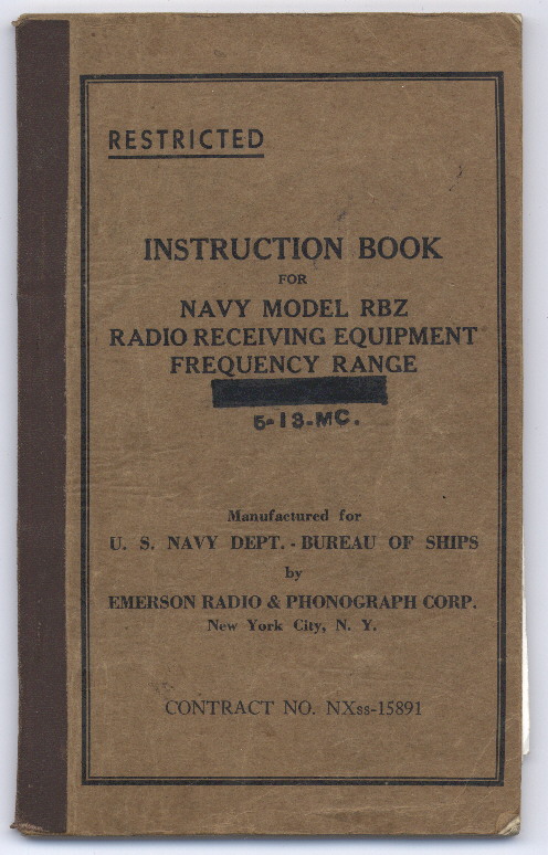
The U.S. Navy RBZ receiver is one of the surplus items crowding my shack. RBZ was produced by Emerson during World War II (I do not know whether it was also manufactured by other companies on licence). It is a 5-tube short-wave AM-only receiver intended for tactical usage. The original RBZ frequency range is 2 - 5.8 MHz, however there also was an RBZ Special version operating on 5 - 13 MHz. My unit is an RBZ Special, and the instruction manual I found indicates the frequency range of that model (see the overstamp on the front cover).
Though not a rare or particularly valuable radio, I believe it is not a very common item as, in my whole radio amateur career, I have only seen a total of two RBZs, including mine. The RBZ Specials are pretty scarce, and they seem to be more common on the American east coast and in Europe; most likely those have been there ever since the clandestine days of WWII.
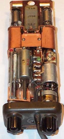
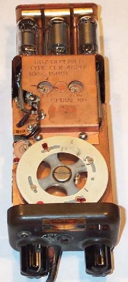
The picture below show the various elements constituting the RBZ: I was lucky enough to find all the bit and pieces, including the canvas holder which is not shown below.
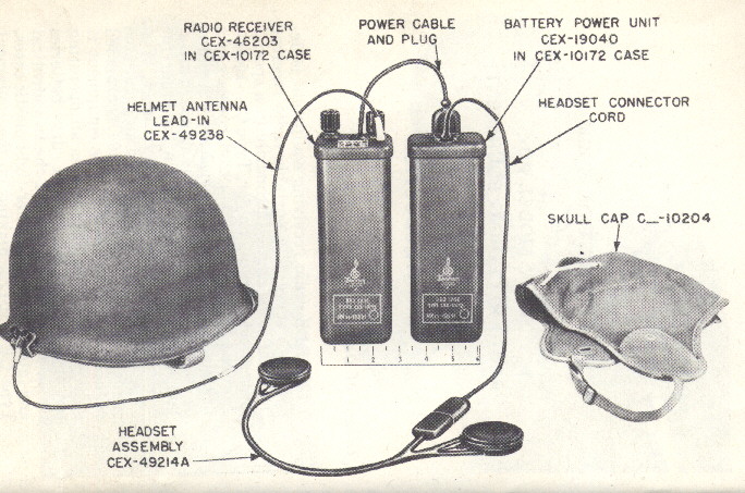
There are two identical plastic (phenolic) water-tight boxes smaller than a carton of non-filter cigarettes, containing the receiver and the batteries respectively and connected to each other by a short 5-wire cable. The headset consists of two earphones kept close to ears by a canvas skullcap. A lead connects the receiver to the "antenna", that is the soldier's helmet!
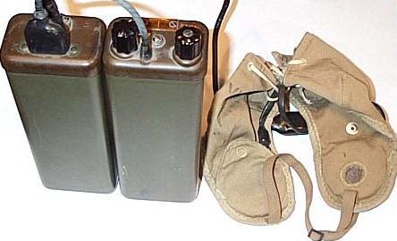
The two boxes were both fitted into a two-pouch canvas holder, as shown below.

Here you see how the RBZ looks like in the reality (canvas holder not shown).
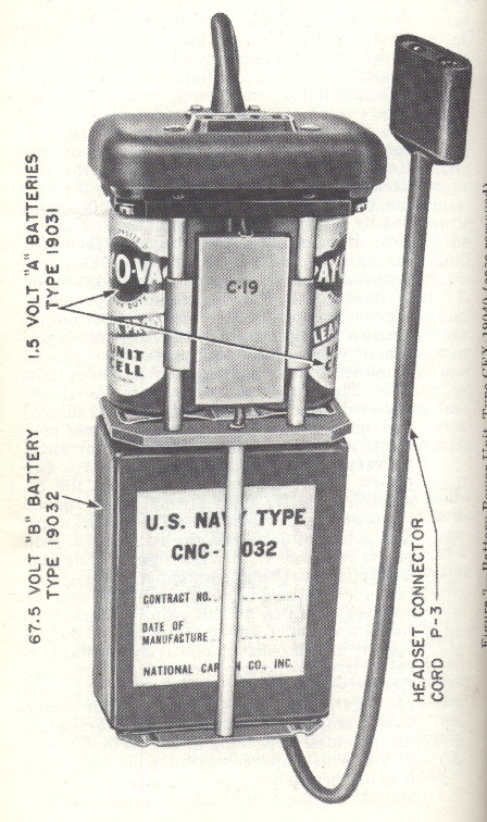
The receiver is powered by one 67.5V battery for the anodes and two 1.5V batteries in parallel for the filaments. All batteries are housed in the same box.
There is absolutely no difference between the RBZ, and the RBZ Special, either physically or electronically. The latter is a simple field modification that involved pasting a paper frequency scale over the existing dial face for the new tuning range, and a re-alignment of the radio. No circuit changes at all were made.
As far as the RBZ Special is concerned, the tactical frequency range of those days was approximately 3 - 6 MHz for radios of this type; then why an obviously tactical radio with a frequency range (5 - 13 MHz) that would not allow using the receiver in a tactical or combat role? They report the story of a Maquis (French resistance unit) using it for receiving instructions for their next supply drop. The RBZ Special frequency range covered that of the BBC broadcast:
"The most important time of the day was when they listened to the BBC broadcast from London that announced their next supply drop. The signals came on three successive days. Their first warning would be a cryptic message: Suzette has hung her washing out to dry (the operation will take place Saturday at the designated dropping point). The following day BBC would announce: There are red flowers in the forest (the drop will be made tomorrow night as planned). On the third day, as they crowded around the tiny RBZ set on their mess table, they would here the final message: Snow will fall in early December this year"
While the above story pretty much solves the mystery of the RBZ Special, it does not do much for the standard RBZ. What did the Navy use it for? Even the initial manufacturing date is not certain. The manual, printed by Emerson, has no dates at all. The RBZ appeared on the June 1944 issue of QST; the Emerson promotional hype stated "Marine Corps raiders and paratroopers now receive their orders over (Raider) receivers", along with the credit for the photo as "Official Marine Corps Photograph". The photo was straight out of the RBZ manual! This proves that the radio existed in early 1944. The only eye witness account, and not from a very reliable source, places the RBZ in use by the shore patrol, Pacific theater, late 1945. An RBZ set was found having a PMS (Preventive Maintenance Schedule) tag on it dating up to 1964, this meaning that they could have been used up to that late date.
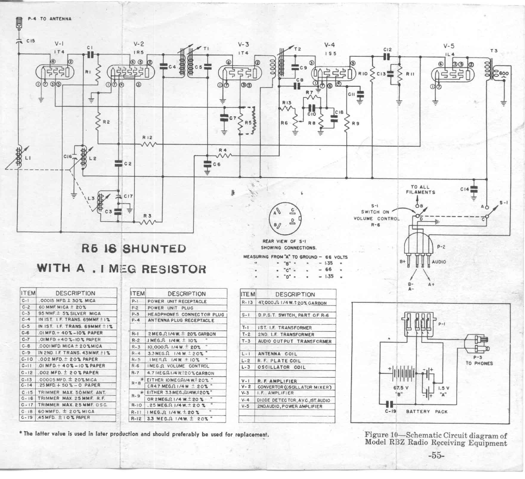
The receiver is a single-conversion superhet, with a permeability-tuned conversion-oscillator ganged to two other variable-permeability coils for the RF amplifier (1T4). The oscillator / converter (1R5) is followed by an IF amplifier (1T4), a detector / AF amplifier (1S5) and finally an AF "power" amplifier (1L4). The whole set consumes less than 10ma @ 67.5 V: looking to the schematic diagram you will realize that resistors were used very sparingly, to limit power consumption as much as possible.
A detail of the front panel follows.
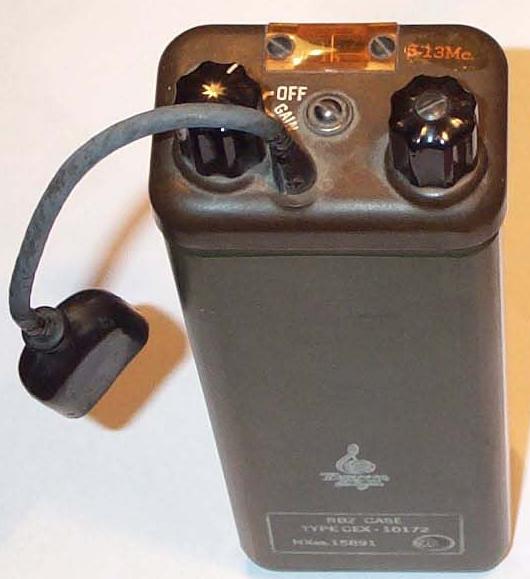
Controls are the minimum, volume + power on-off, and the frequency tuning. The latter is a marvel of mechanical design, it must be pushed in & turned at the same time to engage the internal skunk works, thus tuning the thing, also preventing accidental de-tuning. The dial is the good old Radium illuminated drum type; it is impressive that even with this radio's extremely small size, this dial actually gives you some degree of resolution.
On the air, the receiver is quite hot and one can hear a lot of stations using just a whip antenna.
Now, the power supply... 67.5V batteries are very hard to find these days; you may possibly replace it by six 12V small batteries in series. If you are ready to give up mobility, you may use an AC power supply. By the way, if you are extremely lucky you may find the "original" AC power supply for the RBZ, housed in exactly the same case as the receiver and battery power unit, and operating from either 110 or 220 volts AC. They were designated "RBZ POWER PACK MODEL 2", and also had a headphone jack rather than the standard in line connector.
I preferred to adopt another solution, i.e. that of building a DC-to-DC converter powered by common 1.5V batteries in series, and squeezing the converter and two additional D-size batteries in the space originally hosting the big 67.5V battery. Picture below shows the battery power unit after the modification, with four D-size cells in total.

If you want to reproduce my modifications (at your own risk...), then follow the instructions below. You'll need a GOOD EXPERIENCE in electronics to fit everything within the very very limited space available.
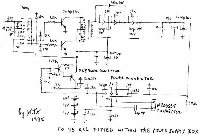
First of all examine the schematic diagram of the modification of the battery housing circuit. As you will see, two extra 1.5V batteries and many components are to be fitted within the room left free by the 67.5V battery.
You'll probably also need to give a look to the original schematic diagram.
The two original 1.5V batteries, in parallel, have the
purpose of feeding the tubes filament. You shall remove the flat capacitor
placed just on the batteries' side (shown in one of the pictures above). That is
C19, in parallel to the 67.5V battery.
Two additional 1.5V batteries are needed to feed the DC-to-DC converter
intended to generate the required 67.5V anode voltage. Such batteries will
substitute the original 67.5V battery; you shall then find a twin battery
holder fitting the available space.
As evident from the modification schematic diagram, the two additional batteries
are connected in series, and in series with the two original batteries, thus
producing a total of 4.5V, a voltage adequate to feed the DC-to-DC converter.
Said converter need only generate 63V, it being placed in series (see diagram) with the
batteries (63 + 4.5 = 67.5).
Let us describe the converter first. A TTL hex-inverter IC (7404) acts as an
oscillator producing two signals having an 180-degree mutual shift. The
oscillation frequency can be adjusted by varying either the 1uF capacitors or
the 4.7Kohm resistors. Play with those values for maximum DC output. The 7404
drives two NPN power transistors (BD135 or equivalent) connected to a center-tap
transformer. The transformer secondary is connected to a voltage-tripler
rectifying circuit.
You must select a transformer small enough to fit the available space, but big
enough to handle the required DC power. The transformer turns-ratio must be such
to produce the needed 63V output voltage. If you have a very high turns-ratio
transformer, a voltage doubler could even be sufficient in place of the tripler.
I advice you to initially build the circuit "in the air" and test
different transformers (from the junkbox) until you get the desired output
voltage under the required current drain, which should be somewhat less than 10mA (you shall have previously determined the receiver current drain with the
aid of a 67.5V workbench power supply and a meter).
The 2N3904 PNP transistor, in conjunction with a PNP power transistor (e.g. a
BD136), realizes
a DC switch, acting such that the converter gets powered by the batteries only
when the receiver volume-control knob is switched ON. A power transistor is
required despite the relatively low current, to keep the voltage drop very low
(about 0.1V).
A simple re-wiring of the receiver ON-OFF switch will also have to be done. Let us first
mark the 4 pins of the power connector as shown below:
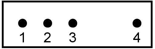
1 = audio line
2 = filaments (1.5V)
3 = ground
4 = anode (67.5V)
The ON-OFF switch has two sections (see receiver diagram), one interrupting the
1.5V filament voltage and the other one interrupting the 67.5V anode voltage.
The filament switch section should be left intact. Instead, the two wires going
to the anode switch section should both be de-soldered from the switch and
simply connected to each other (and insulated). So, the 67.5V line will no longer get
interrupted when the switch is OFF.
The switch section left free should be put in the receiver audio
line (i.e. the wire connecting the 600-ohm audio transformer secondary to pin 1
of the power connector), so that the receiver audio will get to said pin only when the switch is ON (reason will be explained later).
Within the battery housing, as shown in the modification schematic diagram, cut
the wire joining pin 1 of the power connector to the headset connector, and
insert a 50 uF non-polarized electrolytic capacitor there. Such capacitor will
have no effect on the audio signal, but it will prevent any DC voltage present
on the audio line from getting to the headset.
The logic of the DC switching circuit is the following: when the receiver switch is OFF,
the audio line will remain "floating" from the DC standpoint, and the
2N3904 transistor will so keep the PNP power transistor interdict, thus preventing
the 4.5V battery voltage from reaching the DC-to-DC converter. No anode voltage
will then be generated.
When the receiver switch is instead set to ON, the audio line will be at nearly ground
potential from the DC standpoint (the audio transformer secondary takes the audio
line to near DC ground), and the 2N3904 transistor will then react by saturating the
PNP power transistor, hence causing the 4.5V battery voltage to reach the
DC-to-DC converter.
Final note: I determined that several capacitors were leaking due to age (a 10 Mohm resistance is already unacceptable for an high-impedance tube circuit!). I had to replace C6, C7, C11, C12 and C14 (see receiver diagram).
If you hear the DC-to-DC converter whistle in the audio, then put a 1,000 uF electrolytic capacitor between ground and pin B of the receiver ON-OFF switch.
Good luck!
Return to the I0JX home page
This page hosted by ![]() Get your own Free Home Page
Get your own Free Home Page