|
|
Last update: 15/09/01 22.14.00 |
Hallicrafters SX28 - LF
Amplifier & Power Supply
This page is dedicated to
describe and understand the SX-28's LF-amplifier circuit.
Having a look at the
original diagram from Hallicrafters, it was not so clear to me what kind of
circuit it is. So I have re-drawn it in a different and more understandable
way.
This is the original Hallicrafters
diagram  and this my redraw of it:
The two triodes within V12
are configured as voltage amplifiers providing two phase opposite input signals
to the push-pull power tubes.
The preamplifier (and the
inverter)
Let’s examine the first
stage working conditions. The following table compares the conditions as
required by the 6SC7 specs and the value required by the Hallicrafters manual.
By the diagram we can see as the voltage supplied to the triode circuit is limited and stabilized to 200Volts by R38 and
C44.
|
Parameter |
6SC7 specs |
Required by SX-28 manual |
My rig |
|
Plate current (mA) |
2 (max) |
0.7 (read text) |
Not measured |
|
Cathode bias (Volts) |
-2 |
-2 |
-1.6 |
|
Plate voltage (Volts) |
250 (max) |
130 |
127 |
|
Control grid (Volts) |
0 |
0 |
0.01 |
Plate load line:
Let’s take the 6SC7
characteristics and let’s trace the 100K load line for a B+ voltage of 200Volts.
This line crosses the points 200V, 0mA on the horizontal axe and 0Volts, 2mA on
vertical axe. Using the voltages indicated by the Hallicrafters manual (TM
11-874 @ page 34) we find that the no signal working point should belong to the
–2Volts characteristic and at 130 Volts. Unfortunately this point doesn’t
belong to the 100K load line. The condition seems impossible (see pic). Is anybody able to explain me why ?
Looking at the plate characteristics, you can easily verify that the load line
point corresponding to 130Volts plate voltage stays on the 1,5Volts
characteristic line. Under this condition the plate current results 0,7mA that
seems reasonable. Here are the correct working conditions.
Measures in my rig confirmed the values graphically derived (127 Volts on plate
and a bias of 1,6Volts); applying an input signal of 2Volt p.p. the plate
voltage ranges from 95 and 165 volts, in line with the graph; this happened
only at very low frequencies; as soon as the frequency increased over the 50Hz
value, the voltage range dropped significantly. It remains to be verified if
the dropping is compatible with the bandwidth diagram given in TM 11-874
manual….
The bass control circuit remains to be clarified. It look like there is an
error in the Hallicrafters diagram. I am submitting questions about this topic
to relevant mailing lists and I ‘all report foundings as son as they’ll be
available.
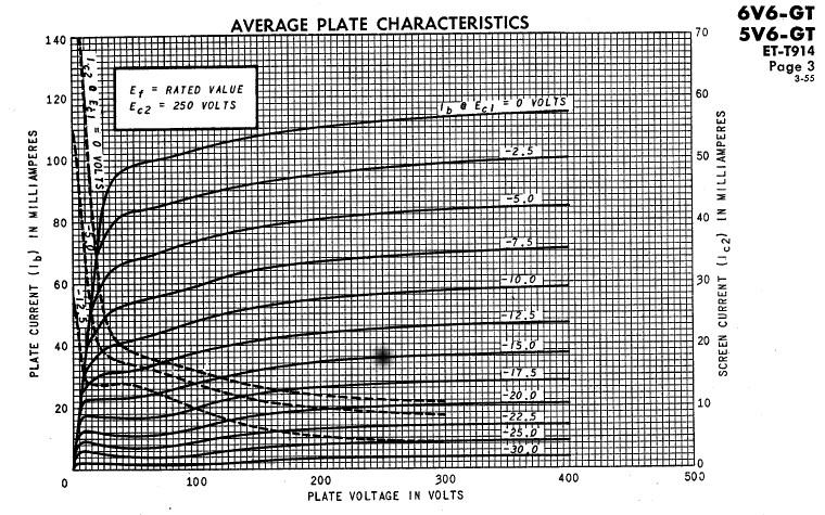
The power amplifier
The push-pull working condition
is class AB1. The working condition chosen by the designers is the one
highlighted on this
6V6GT specifications. Those values exactly match the SX-28 specifications:
the output choke specs as well as the voltages required by the SX-28
maintenance manual.
Here are the figures:
|
Parameter |
Required |
Measured my rig |
|
Plate current |
35 mA |
32 mA |
|
Cathode bias |
15 Volts |
14.5 Volts |
|
Plate voltage (Vs
Cathode, not GND!) |
250 Volts |
250 Volts |
|
Screen grid |
250 Volts |
264Volts |
|
Control grid |
0 Volts |
0.014 Volts |
load dynamic line:
In tube power amplifiers
with an output transformer, two different working conditions have to be
considered. The first being the one with no signal, the second including
signal. This is due to the fact that the amplifier load is constituted by the
primary of the output transformer and thus inductive, meaning that the load dynamically
changes with the frequency or without. This means that you don’t have a single
load lines, but two.
Let’s find the no signal
working point. With no signal the tubes have no load (I consider the primary
resistance equal to 0) so the entire voltage coming out from the power supplier
is applied to the plate. The load line for load=0 is a vertical line passing
through the power supply voltage B+=250Volts. The point we are looking for is at
the intersection between this line and the tube characteristic of the specified
bias, -15Volts in our amplifier. The load line we are looking for has to pass
through this point. But with which inclination?? (see pic)
With a dynamic load
impedance of 10K plate-to-plate each tube sees a 5Kohm load resistance. To find
the line we can temporarily assume that the 5 Kohms load of the single tube was
purely resistive. In that case the load line should have been the one crossing the points 250V, 0mA on the horizontal
axe and 0Volts, 50mA on vertical axe. This line is not the one we are looking
for as it doesn’t pass through the resting point, but it has the correct
inclination. So the dynamic load line is the only line passing through the
resting point and parallel to the 5K line we just plotted down.
Don’t get surprised that with that line it seems the power supplier supplies
more voltage than it is expected to do. In fact it supplies the correct
voltage, but the inductance effect of the choke’s primary increases the plate
voltage that way. Think of it has an attempt of the inductor to compensate for
the current reduction during the falling part of the signal slope.
With regard to the output
transformer, we can say that its primary must have an DC resistance of 500 ohms
and 10000 ohms as impedance plate-to-plate. Its windings ratio should be given
by the formula: n=SQRT(Rl/Ro) where n is the ratio, Rl is the required load
impedance as per the tube specs and Ro is the output (speaker) impedance. This
means that the original choke should have n1=SQRT(10000/500)=4.5 and n2=SQRT(10000/500)= 1.4 for the 500 and 5000 ohms outputs. If you
want (or need) to substitute it with a 8 ohm output, the formula becomes:
n=SQRT(10000/8)= 35 (it can be challenging to build such a choke in the same
space as the original one… some people
report Hammond has made such a transformer for their guitar amplifiers…).
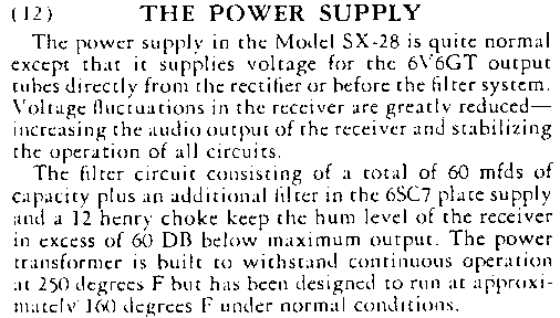
Here is an excerpt from the
user manual (as you can find @ bama)
describing the LF-amplifier and the power supply;

Waiting for the net to
clarify:
- what is the C40 function?
- What is the C76-R43 network useful for?
- Why R37 is shorted when the
"bass" switch it in the OUT position? Shouldn't it remain in for
the sake of symmetry with the inverter plate resistor R36? Note the red
marked voltages - the are different due to the different plate loads on
the pre and the inverter due to this asymmetry.
|
|
Last update: 15/09/01 22.14.00 |