FT-707
This was Yaesu's replacement of the FT7B. So what's special about this
old horse? Nothing, actually. But it does offer the few features I need,
including a 600Hz 8.9 MHz IF filter. It’s quite compact, although it does
weigh over 60N. The bar-graph LED meter is great for monitoring relative
power out, being fast to respond to voice peaks, but isn't so pleasant to watch as an S-meter.I see that Yaesu reverted to a
traditional moving coil meter in the successor FT-77 radio.
I owned the Scanning VFO Memory, FV-707DM, for a few months. It had eleven
memories, and could split tx/rx between it and the
analogue VFO. I don't recommend its purchase, it's a gimmick. The analogue VFO frequency cannot be dumped into the FV-707. It can only be tuned using the up/down buttons, which is slow. It’s noisier than the analogue
VFO, and funky chirping noises are heard as frequency is changed. The 100Hz step change
was too coarse in my opinion. Rather make yourself an analogue external VFO, the rear panel has an accessory DIN socket to support external VFOs. Inserting a DIN plug will switch the internal VFO out of circuit, the required VFO can then be selected by putting a few volts on the right pin of the ACC socket. Here's a suitable VFO circuit with switching between the FT-707's internal and external VFOs.
G3TSO published mods to include the 1.8MHz band,
mimicking the FT-107 circuitry, and I recall that 'Amateur Radio'(?) magazine published a mod to receive
50MHz, with 1mW available on transmit. I thought it used one of the existing LO
crystals, but took the image product, so that the VFO would tune 'the wrong
way round'. I can't see what band crystal it was! 53.9 MHz is needed if the tuning is to be inverted; 36.1MHz is needed if tuning and sidebands are inverted; 46.6MHz is needed if sidebands are inverted.
70MHz operation
If you're feeling particularly in need of a challenge, how about an FT-707 on 70MHz? This would require a 84.4MHz local oscillator, with 'high side' mixing. Pre-mix becomes 84.4 - 5.3 (vfo) = 79.1 , and output RF = 79.1 - 8.9 = 70.2 MHz.
Note that the VFO tunes 5-5.5MHz, where the lower vfo frequency translates to the radio operating at the top end of each 500kHz band. I admit that filtering out the 87.8-88.1 image may be a problem in some areas. 88.1MHz (imaged to 70.3MHz) is used for BBC Radio 2 from Sandale (250kW) for SW Scotland, and from North Hessary Tor (160kW) for Devon. This is the method used by the '707 on HF, so it would be interesting to establish if the digital display could be made to work. Alternatively, a local oscillator on 66.6MHz, with 'low side' mixing, would maintain the VFO dial tuning in the correct sense, but would invert the sidebands. This method puts the image on a more practical 52.2-52.7MHz. But that's a hassle for CW on VHF where you really want to be listening on USB for those 'cross mode' contacts.
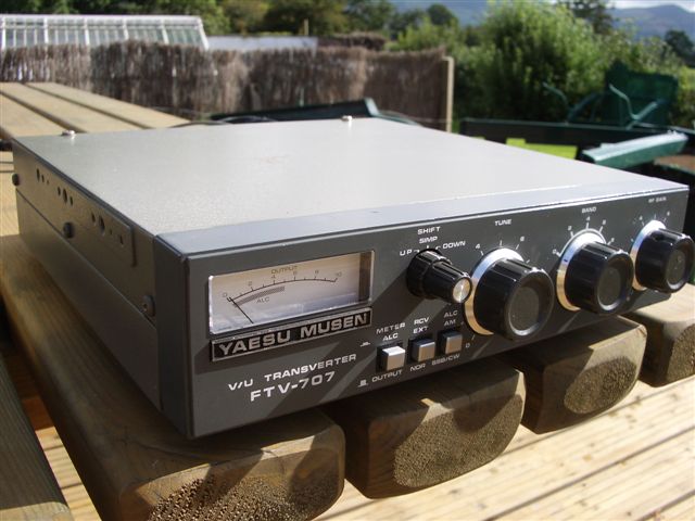
FTV-707
FC-707
Comment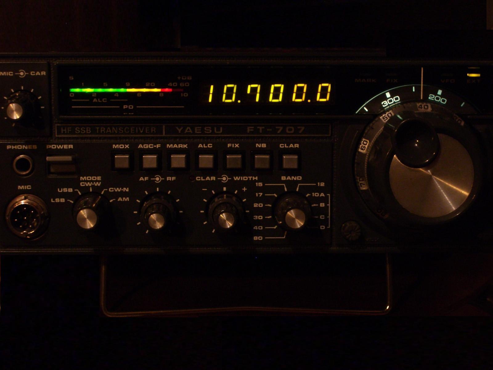
This is the accompanying transverter, and its physical construction is excellent. One RF band module can be plugged in at a
time, and the module takes 1mW of drive for 10W of output. Note that
the FT-707 transverter output is tapped off from
the feed to the PA board. There’s more drive available here if the resistor
values just behind the phono socket low-level-out on
the FT-707 are altered. This is also a good point at which to vary provide the '707 with HF power control.
Interfacing of the FTV-707 with the FT-707 is amazingly straightforward. The HF antenna is now connected to the transverter rather than the transceiver. DC power from the power supply is connected to the FTV-707, and an integral lead then feeds that power on to the FT-707. Four pin power connectors are used on the radio. One pin is reserved to carry a low current DC-on-TX signal from the FT-707 to switch the FTV-707 to TX. When the transverter is switched on, then that DC signal is not fed back to the transceiver's PA, preventing it from ever transmitting into the receive converter. Whilst the transverter is switched on, relays within it also bypass the HF antenna, and the downconverted VHF signal is passed back to the FT-707's antenna socket.
Conversely, with the FTV-707 switched off, the DC-on-TX signal from the transceiver is looped back to its PA, and the HF antenna looped from the FTV back into the FT-707. This obviates all the hassle normally associated with using a transverter. Similar methods are used in Yaesu's FTV-107 and FTV-902.
You could conceivably run two FTV in parallel,
transmitting on two bands simultaneously, and switching between either
receive converter to listen for replies. A more elaborate extension of
this idea would be to use a second 28MHz receiver, affording simultaneous dual
band transmission, and receiving audio from the separate radios through the left
and right ears of a stereo headset. Good for multiband, such as the RSGB Christmas Cumulatives, when you want to work as many bands as possible, during a two hour window? This would be similar to military Air
Traffic Controllers, who routinely make simultaneous transmission on VHF (civil) and
UHF (mil), such that the pilot hears all the controller's transmissions, but can’t hear
pilots on the other band.
The frame includes an 'external' button, which bypasses the receive
converter, connecting the HF antenna instead. I've used this facility to
connect my Meon 50MHz up as a receive converter,
and switch between 50MHz and 70MHz quite quickly. GB3BUX can be compared on
its 50.000 and 70.000 frequencies very easily in this manner, and cross
banding is made quite straightforward. Very conveniently, when the transverter is off, the HF PA is enabled, so there’s no
antenna cable switching required, or danger of inadvertently transmitting
100W into the receive converter.
Within the frame, a shielded box houses an ALC module,consisting of one bipolar stage which
throttles the drive to the RF module. Yaesu should
have taken the ALC from the RF module output, and fed it back to the FT-707
IF board, rather than to this down-stream limiter. The FT-707 low level
output gets dirty when the Carrier/Mic Gain pot is advanced beyond the twelve o' clock
position, and no amount of action by the ALC in the FTV frame is going to
clean this up. When using my home made transverter,
I feed a sample of its fwd/rev voltage back to the FT-707 ALC on the IF board, via the rear
panel accessory DIN socket. This is simpler and more effective. Yaesu could have routed the ALC back to the FT-707 by superimposing its negative DC signal on the transverter RF tx line. The transceiver’s meter can now be used to show ALC action
ALC, otherwise its LEDs show nothing during transvert TX.
Other front panel controls include pots marked 'Tune' which peaks the transmit side using varicaps. This is pretty redundant on the limited UK 6m and 2m allocations. To the right, the 'Band' switch selects the respective LO crystal for each two MHz band section. A 'Shift' button can select two possible additional crystals for use on TX. Presumably this was meant for repeaters, although the FT-707 never came with an FM facility! The right-most pot controls the RF gain to the front end 3SK51. A tidier design would have included a link back from the FT-707's AGC line to the transverter, not left it to be controlled by hand. It's clear that the transverter was an afterthought to the original HF transceiver. So, plenty of spare front panel switches and pots if you wish to try some ideas.
I hacked a 2m module to work on 4m. The PA 'brick' had to be discarded,
although in retrospect, in the spirit of Living Beneath One's Means, I should perhaps have sawed it open to see if it could have been retuned. A 2N6082 stage built on to the original heatsink.
Another 2m module remained untouched. A pity that the transverter frame wasn't large enough to house more than
one module; I understand that three can be fitted in the FTV-901 and
FTV-107. All these plug in RF modules are of obsolescent receive design - 3SK51 front end and
3SK51 mixer. There is plenty of space to change these, however, if you want to muck about with
more modern devices and mixers, although the limiting factor for most users will be the 3SK73GR front end in their FT-707.
That 4m transverter was sold on eBay in 2012 to a Greek amateur for a staggering £159!
Surprisingly popular on the second hand market, this antenna tuner is fitted into an identical frame
to that used in the transverter. Inside
there's a T-network, a relay switched dummy load using 8V feed from the
FT-707, and an illuminated Power / SWR meter. 200W or 20W fsd. Don't try to tune any balanced feeders with
this tuner, it's only designed to improve the matching to unbalanced feeders.
But let's face it, if your antenna's properly designed, you don't need an ATU. Perhaps it's useful for mobile installations. Quite a useful power meter, at least, and very neat with its faint green backlighting.
I should also mention that the FT/FV/FTV/FC range all have two threaded holes on left & right sides for mounting together via brackets for mobile use. Easy to construct your own unit to keep them together, but far enough apart to avoid any heating problems.

I feel that my 40 yr old radio has aged quite well. Certainly better than I have. I never much liked the receive audio, despite having complements about the transmitted audio. But more lately I'm using the HT10-40A headset all the time, and the sound really is pleasant. My VFO has developed a little backlash over the years, about 200Hz at one point each rotation.
Probably I must be the only radio amateur around who's never changed his '707 for something more modern in all that time. But 100W is still 100W isn't it? I'm not interested in FT8, and the bands are noiser now than they ever were. I think the days of talking to VK each morning on 20m are probably gone.