FT-225R FT-225RD 70MHz conversion
Introduction
The Yaesu base stations from the early 1980s were fitted with plug-in boards. I presume the logic was to have a common main deck to reduce production costs, and then to populate with boards depending on what band the radio was to cover, since similar layouts were used for the FT-101ZD, FT-902DM and FT-625RD series. It certainly makes it easy to remove boards for maintenance, or to replace them with your alternative. The 70MHz band has traditionally been neglected by the big amateur radio manufacturers; it used to involve a little more effort to be QRV than on the other VHF bands, consequently one tended to meet more technically minded folk on this band.
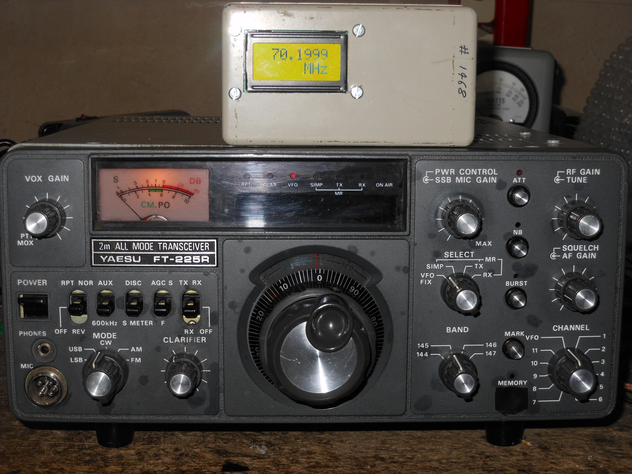
The FT-225R series lend themselves to straightforward conversion to 70MHz, especially since there's no freq display to modify. Indeed there's adequate space to fit an after market freq counter.
This was GW4HBZ's radio. I remember it working into Italy, barefoot, on TROPO during those great openings of the 1980s. Anyway, he'd gone QRT and wanted to dispose of it.
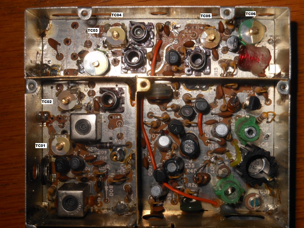
Local Oscillator Board
I've since screened the lower right side of the board to reduce stray coupling to the adjacent PreMix board; they sit back to back, unfortunately.
Pre-mixer Board
Rx Board
Exciter Board
PA Unit
Rear Panel
For the radio to tune 70.0 when the VFO dial skirt reads 'zero', a 51.1Mhz LO is needed, although provision was included for up to three 3rd overtone crystals, to cover 69-70-71 MHz, on the Band Switch 144-145-146 positions. A single stage of MPSH10 was used to give 2dBm out. RIT provided by BA244. Sensitivity was well down on 69 and 71MHz, since alignment was carried out on 70.2MHz. To get it working properly on 69 & 71MHz, the 'Tune' DC line would need to be brought into service, along with a PIN diode across the collector of the transisitor.


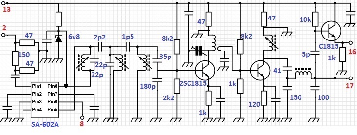
The PLL board was discarded in favour of a SA-602 to mix in the 8.2 MHz VFO, of which just a sniff is needed. Before the attenuation at Pin 1 of the SA-602 was fitted, horrific IPs were being generated from 7 x VFO.
After three poles of filtering, the PreMix level was ~ -20dBm. A MPSH-10 raised this to ~2dBm. Spurii >50dB. Subsequently, I found the power dropped to -3dBm, I never did find out where that went to, but gain is cheap, so an additional low Ft, stage was added before the MPSH-10. The board can now produce over 7dBm out. Buffered output for a frequency counter is included.


Some of the existing trimmers were very stiff, their dielectrics fractured upon tweaking, so they were replaced by Muratas.
I ended up completely rebuilding the first stage since I wasn't satisfied with the existing performance - there were plenty of losses before the signal even reached Q02, a 3SK51. Varicap diodes D05 & D06, L03, L04 were removed. Two tuned stages are dropped in favour of one. L04 is replaced by a Ag-plated airspaced coil. The other three varicaps were pulled to ground to achieve their maximum capacitance. Q02 was replaced by a BF-961, soldered underside to avoid drilling holes to fit its wider pins.
Note that there's sufficient space to fit a DBM, should one feel the urge to replace the MOSFET mixer.
The receive path is intercepted after the PIN diode attenuator, and re-routed to a BNC socket on the rear panel. This is looped back to an N-socket that feeds directly to the front end coil.
If the lowest loss possible to the Receiver is desired then remove the loop, and feed the front end directly from the N-socket, thereby avoiding the PCB antenna relay, the Booster's "valve" socket, the plug-in board and its PIN diode attenuator. If using an external power amplifier, the losses of two relays could be avoided by this method.
The difference is appreciable on extremely weak signals. A Rx only BPF could be looped in at the rear panel if necessary due to local interference.
The receiver performs very nicely. That rich FT-225 sound, but now on 70MHz. 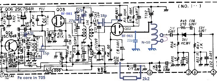

This is more involved than the receive side. I doubt that there is need for four poles of filtering after the push-pull mixer, but I've used them all since they're present. All the ceramic trimmers were replaced by Muratas. The schematic shows the padding capacitors used with the original trimmers, in case yours are capable of being tweaked without suffering the dielectric cracking that I experienced. The new trimmers are accessed from the front, rather than from above, so an extender board is now required for alignment.
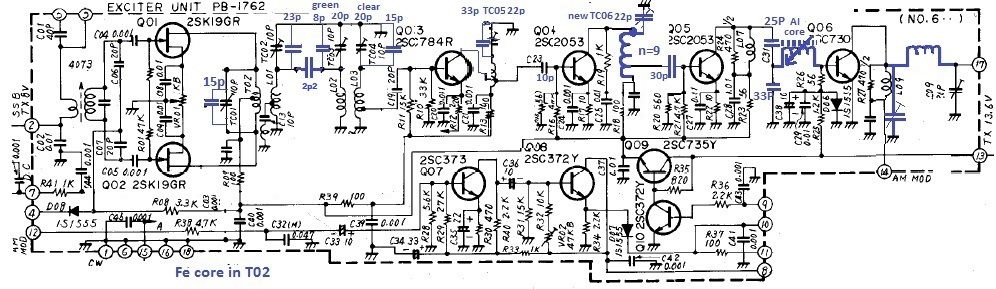
A wire is taken from Pin 15 to the Power Control potentiometer, and then back to Pin 15's original two yellow wires. Originally, power control worked on CW/FM only, perhaps this was a design oversight. In any case, all-mode power control's essential for setting the drive to an external amplifier. The original and modified Exciter produce 1W out.
Well done for reading this far, we're nearing the end now.
L05 & L07 collector chokes were rewound with ~8t 1/4" spaced. L06 & L08 were replaced by L09 & L10 (4 turns, 1/4" internal diameter). 60pF trimmers used in place of C01, TC01, C48, TC02, TC04.
The funky FM/CW-only power control circuitry that clipped the signal before Q02 has been removed.
An unreliable antenna relay meant that it had to be replaced. A most miserable saturday evening was spent first extracting its PCB from the housing, and then rerouting ant/tx/rx and supply lines underside, since my replacement DPDT relay had a completely different pin out. Both poles are paralleled, to distribute the RF power and increase reliability. This is a 5V relay, powered at 5.1V; it will switch reliably down to 3.84V, just in case the radio should ever be operated on a sagging 12v car battery rather than a 13.8V PSU.
Once this difficult-to-remove-sub-board was reassembled, I realised that I'd omitted to redimension that sub-board's LPF. In disgust, I bridged out this section and quickly put the lid back on.
Not shown is 15nF in series with 300ohm across the Q01, to quench any tendency to misbehave during rx.
The radio easily produces 30W.


A BNC socket carries buffered pre-mix out. Alternatively, this socket could be used for IF out to a SDR.
The AC fuseholder has been removed, since in the UK we prefer our fuses safely within the mains plug, not waiting to bite us in the radio.
The DIN socket was then moved one slot along, freeing space for the BNC to N-type Rx loop.
The CW Key socket (3.5mm) is located where the Ground terminal used to be.
The sockets aren't actually labelled; the script was added to the jpg just for the internet.
Repeater Board
This remains in place, although there's no longer any down shift if the Repeater switch is thrown. Note that there's an FM tx audio stage located on this board, just in case you thought that this board is now redundant, or thought that you could employ its space for something more useful, such as a diversity SSB receive IF?
Summary
The radio's lovely to use with its silky smooth VFO.
In common with most of the '225s that I've seen, it had no MEMory unit, so an External VFO was was added.