GW4RWR -70MHz 4m GS31B Amplifier YU1AW design
Introduction
Why go to the effort of putting a largeish triode on a band where the power limit is 160W? It's a fair question. Perhaps it's just for my own amusement. Most cars easily exceed the speed limit, but they're not driven around at those speeds. I wanted to achieve a clean, legal limit signal. I also recall hearing that the power limit might even be raised to our standard 400W, but that was years ago, it's never happened.
Results?
There's no expensive bias board here, since that would have cost more than my valve and its spare, put together. Rather I'm using two 2N3055 with each collector tied to base, and emitter tied to cathode. One device has a Vbe of 13V, the other has 22V. In series these hold the cathode 35V above grid (ground). I find I need the 35V, infact more could be useful at the 4kV+ HV level.
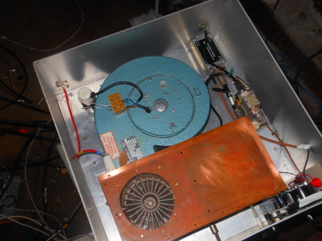
The directional coupler has four coupled outputs; two are used to measure forward and reflected power; two others protrude through the rear panel and feed to a spectrum analyser, or a CRO for peak power measurement. Also visible is an additional N-type above the o/p N-type, this allows me to bypass the input relay, and route the Rx path straight out if I want to minimise losses.
The GS31B is one of the cheap Russian valves sold as 'new old stock'. I think I paid about £35 for this one. Apparently it's electrically very similar to the GS35B, but has a smaller anode cooler, dissipation is quoted as 1kW. Not many amplifiers are designed for this smaller tube, but it's substantially cheaper, and may have longer life expectancy. So it may offer better value?The filament runs on a convenient 12V.
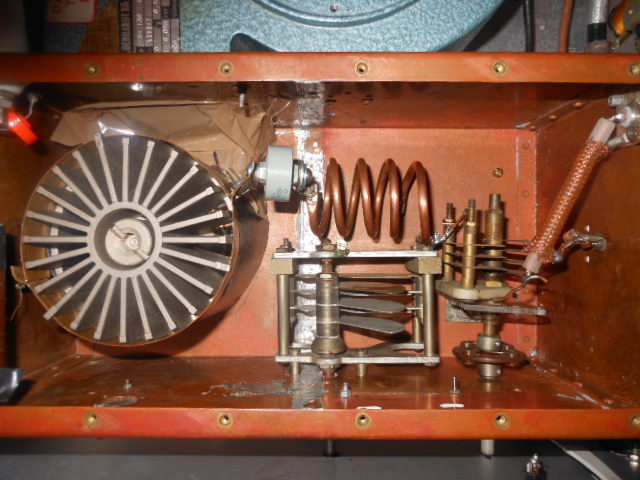
This cabinet was welded together from four 3mm aluminium blanking panels,with a thinner plate for the floor, welded about 1/3 up from the bottom. Base and top plates have folded in edges to give a tight fit, with self tap screws holding them firmly in place. A diecast box encloses the cathode, and a copper box takes care of the output side. The amplifier was built late in 2006. In 2013 it was some further work - the tuning capacitor was changed for one with wider blade spacing; the reverse power meter was added; cathode tuning was brought out to the front panel for ease of operation.
A directional coupler can be seen in the third photo. This has four coupled outputs; two are used to measure forward and reflected power; two others protrude through the rear panel and feed to a spectrum analyser, or a CRO for peak power measurement.
.
With 4.2kV on the anode:
50mW drive from a 2N3866 gave 2.5W out, so about 17dB gain at low level.
I've only got a RA30H6080m for drive, so am unable to say how much power this amplifier is capable of producing. The amplifier has been mounted at the top of my 19" rack for almost ten years; tune/load controls haven't been touched in all that time!


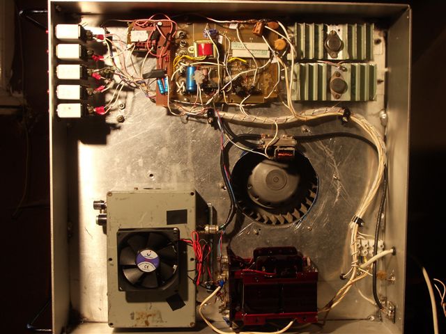
That board is a mess, I must redo it. An extra transformer and voltage doubler was needed since my main antenna relay wouldn't pull reliably until I had pver 40V on it. I should use timers for soft start switching, rather than all the manual front panel switching employed.


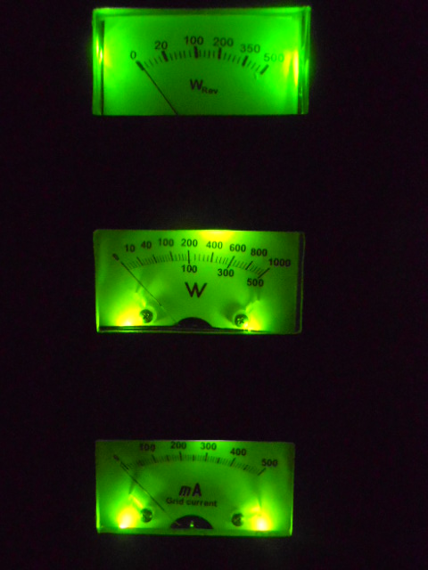
The 1mA meters are mounted behind the front panel for tidier appearance. This also made it easier to illuminate them all. LEDs aren't confined to the base of each meter, some are glued much higher up the sides.
.