Renovation of a KW Viceroy MkII - December 2016 GM3WOJ
Click here to read about the renovation of two KW Vanguards
Firstly - many thanks to Lawrie G4FAA for supplying me with original circuit diagrams and documentation for the Viceroy MkII.
This KW Viceroy was rescued from a friend's shed in New Zealand in 2005 and is in poor condition - but I like a challenge and it is enjoyable getting it working again. Older, rustier, more corroded = more fun!
Scroll to the bottom of this page for a couple of KW 1000 amplifier photos.
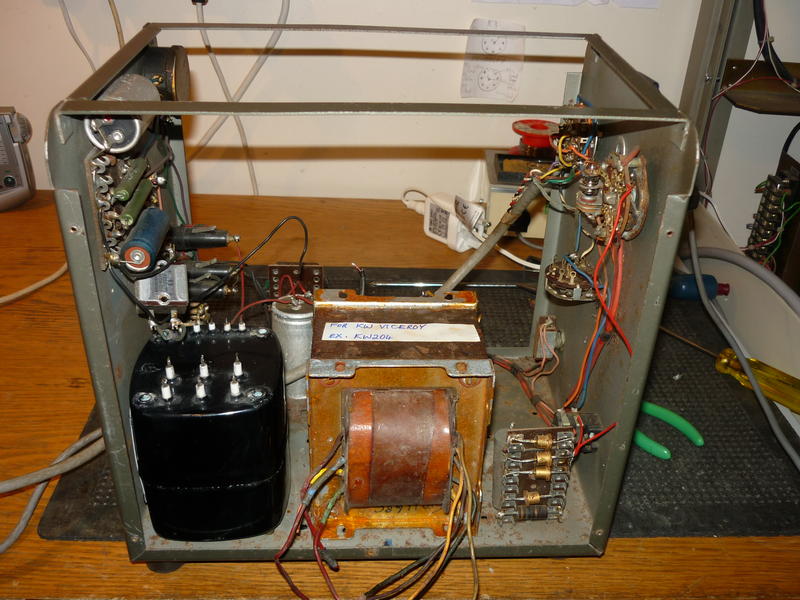
2nd December - the photo below shows the PSU of my KW Viceroy MkII being rebuilt in time for use by GB2KW during January 2017. Just before 'KW Day 2016' (the first weekend in January) the xfmr which supplied the heaters, +250V rail etc started making fizzling noises and died. I am replacing that xfmr and also the existing HV xfmr with a Gresham oil-filled 6.3V xfmr and all of the HTs/bias etc AC voltages will be supplied by the ex-KW204 xfmr shown in the photo. The Selenium rectifier and the HV capacitors will all be replaced and the wiring tidied up.
5th December update
The PSU as shown above is now rewired with new HV capacitors and new diodes, but not yet fully tested.
The photos below show the current condition of the KW Viceroy MkII - this is *after* I have give it an initial clean up, replaced some valves where the gettering had gone white, and reconnected the Eddystone 898 dial drive cord (which is still not 100% correctly tensioned). The brown marks on the front panel (apart from the rust at the bottom) are nicotine stains or old varnish I think - so far they have resisted every corrosive chemical I have tried to remove them with. The PA anode clips and anti-parasitic chokes have desoldered and fallen off as you can see, but are easily reconnected.

Doesn't this TX look great ?!

When I powered this TX up for the first time in January 2016, I was amazed at how stable the VFO was. Fortunately, the underneath of the chassis looks a lot better than the top.
One problem I am overcoming is that the new Gresham heater transformer cannot supply enough current at 6.3V AC for the 14 valves in the Viceroy. There were 2 separate 6.3V windings on the original transformer which died - each winding feeding about half of the valves via 2 separate wires in the multicore cable which joins the PSU to the TX. The total heater current required is just over 6.6A at 6.3V - with the Gresham transformer (which has 3 secondary windings), one half of the valves are measuring 6.3V at the heater pins, but the other half of the valves are only measuring 5.7V. These valves will still work of course (e.g. a 6146B heater voltage is specified as 6.3V, but with a range of 5.0V to 8.0V) but obviously anything other than 6.3V +/- is not ideal. I have some other 6.3V xfmrs that would supply more current, but they are physically too large.
My solution is to use the 12.6V AC winding on the ex-KW204 xfmr, which is unused at the moment. This involves re-wiring half of the valve heaters to run on 12.6V instead of 6.3V. Luckily, the 6 valves at the right of the TX as in the photo above, are fed with a separate line (pins 2,3 on the power plug) and can fairly easily be rewired to 12.6V. Specifically, V7 and V8 (12AU7s) - heaters now in parallel across 12.6V, V9 and V16 (6AL5s) - heaters now in series across 12.6V and similarly V12 and V13 (6146s) heaters now in series. The rewiring is tricky, because when the Viceroy was manufactured the heater wiring would be the first wiring to be done, so you are working underneath other wiring in most places.
20th December update
Well the rewiring of the heater circuit went well and the Viceroy is producing RF. There were a series of problems to overcome - here are two of them and how they were fixed, if you are interested :
(i) Carrier balance control not working. This was traced to a dud OA79 germanium diode. Both balance modulator diodes (which are on a removable plastic B9A plug) are actually still diodes, but when tested one of them was very different from the other. I replaced them both with 1N34A diodes that I happened to have. Now the front-panel carrier balance pot works and when combined with the compression trimmer gives reasonably good carrier suppression.
(ii) Ferrite cores of 435kHz IFTs stuck. There are 5 IF transformers, although only 4 of them have both top and bottom cores. These ferrite cores are quite long (17mm) and were inserted by the manufacturer with rubber bands beside the core to hold the core in place after adjustment. Surprisingly, some of these 54 year old rubber bands were still intact, but some had disintegrated into a very sticky mess which made turning the core impossible. The alignment of this part of the Viceroy is probably the most critical factor in producing reasonable-sounding SSB, so it is essential to be able to adjust *all* of these cores. I was planning to drill out the stuck cores and replace them with new ones until by chance I mentioned the problem to Ron GM4ILS (who has many years of experience of repairs) and he suggested using a small amount of WD-40 to soak the stuck cores overnight. This worked well - I was able to remove the stuck cores, clean them then re-insert them the other way around (not really necessary cos I have been very careful not to damage the small slot in the end of the core - I used a plastic knitting needle with the end shaped to fit the slot in the core precisely) I will use melted candle wax to keep them in position after I am confident the IFTs are correctly aligned.
Next I am following the alignment instructions carefully. There is some ambiguity in the information - I will clarify that here once I have more information.
30th December update
Well because of Xmas family visits, etc. I have only partially completed the alignment. The SSB sounds good when monitored at 435kHz, but at the moment the Viceroy is producing zero RF on 80m. 80m should be the easiest band to get working, because it is just CO + VFO. [40m is the unusual frequency generation scheme, being (2 x HF Osc) - (VFO - CO)] Most of the HF coil ferrite cores are stuck in their coil formers, so I need to loosen them in the same way as I did for the IF transformer cores. Strangely the Viceroy produces RF on 40, 20 and 15m, but when viewed on a scope the RF is there all the time i.e. either a parasitic oscillation in the PA or some unwanted mixing product caused by misalignment.
1st January update
One frustration is my inability to generate a stable signal at 435kHz +/- (or to sweep the half-lattice xtal filter) - both my clunking HP8640A and HP8640B signal generators run out at about 448.5kHz and my Thandar function generator, although it gives a stable signal at 435kHz, is very difficult to set accurately. I'll try to get a Marconi 2020 or similar signal generator, which apart from anything else is much smaller than the HP ones.
The KW Viceroy alignment is on 'hold' while I sort out the other GB2KW equipment and the antenna switching arrangements so that we can easily switch antennas between the different KW stations.
____________________________________________________________________________________
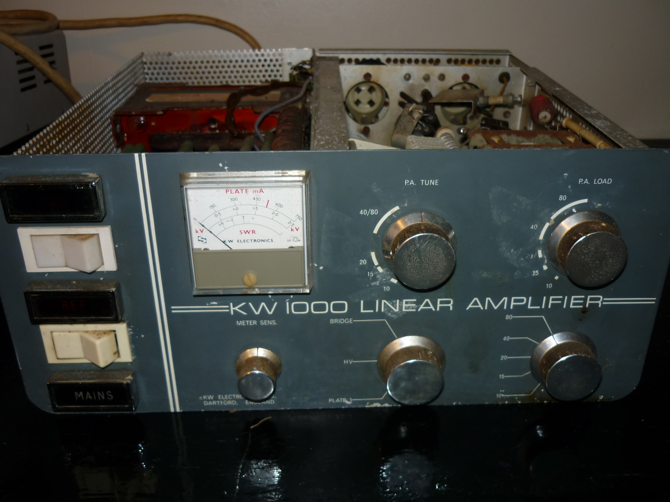
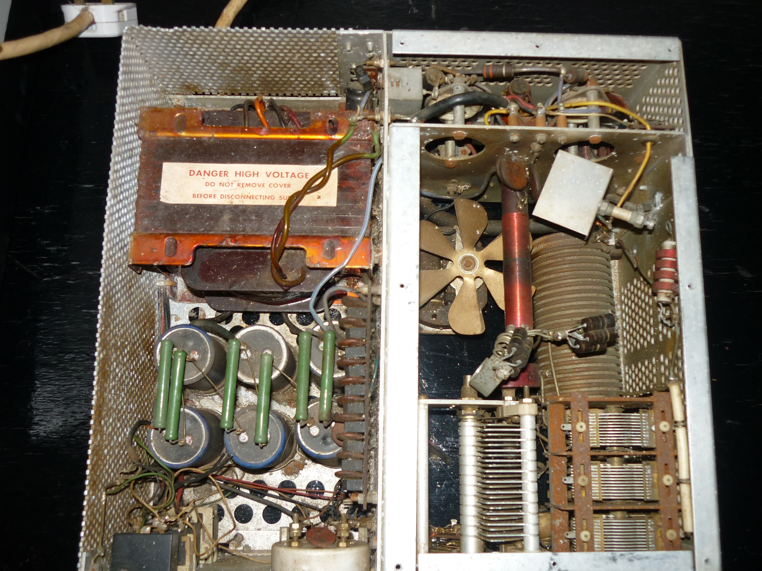
KW1000 linear amplifier
I thought you might be interested in a couple of photos of the sad-looking KW1000 amp I have. I have about 5 good 572Bs, so if the transformer is OK I see no reason why this amp should not be made to work well. These photos show the amp after I've given it an initial clean-up, with lots more work to do :
More info soon....... 73 Chris GM3WOJ