Kokusai MF-455-10CK Mechanical Filter repair - February 2016 Chris GM3WOJ
This webpage describes my experience of repairing the type of mechanical filter used in the KW2000 series of transceivers. There are other articles online, but I could not find any which had detailed photos of the procedure - probably because these articles were written in the pre-digital camera era. I would rate this repair about a 7 out of 10 for difficulty, but it all depends on how carefully you handle the dismantled parts of the filter.
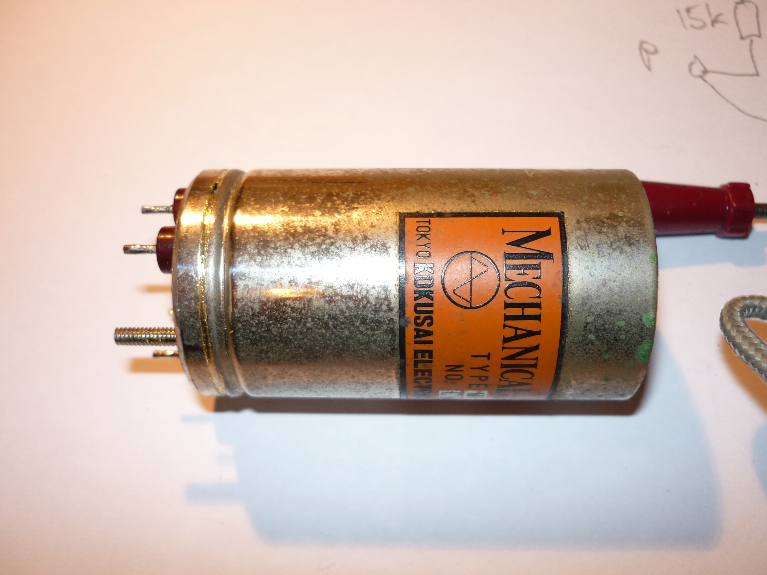
There are variants of these Kokusai filters, which are also used in some other KW equipment. I am bringing back to life a recently-purchased KW2000A - serial number A428 - which has probably been lying unused for a number of years. It has been modified in some strange ways, with generally poor soldering - I am slowly returning it to original condition, as much as is possible. After fixing an annoyingly loud hum loop, it was evident that something was fundamentally wrong with the transceiver - the RX was totally deaf - the Kokusai filter was the prime suspect.
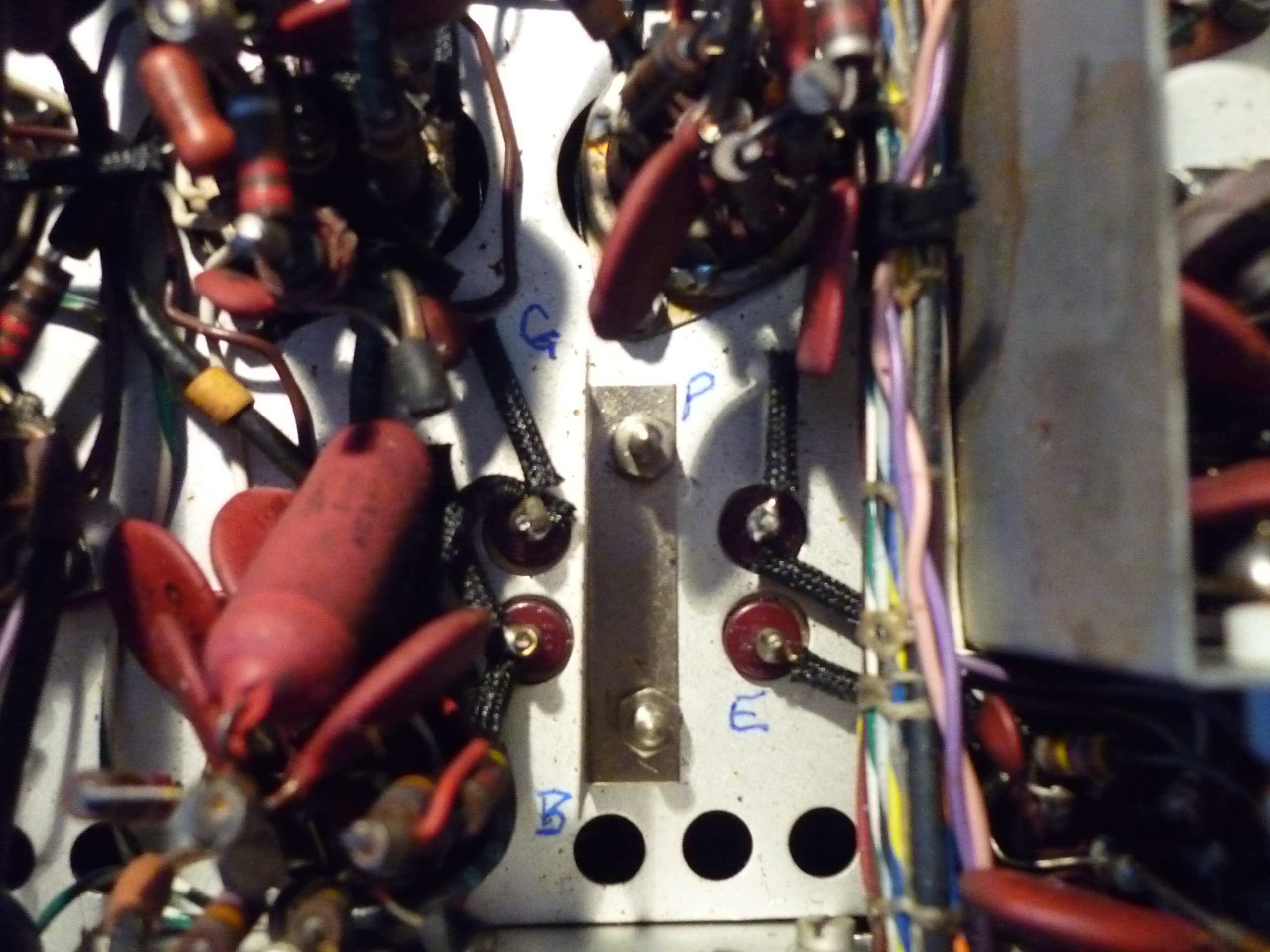
1. Ascertaining that the mechanical filter is definitely faulty. Considering that all of these filters are 50-odd years old, it is highly likely that your filter is faulty, but it is a good idea to check. As recommended in a very helpful online (PDF) article by Graham G4EUK titled 'Kokusai Mechanical Filters as fitted to the KW2000 series of transceivers (including the KW202/204 and Vespa)', I soldered a 0.01uF 500V silver mica capacitor across pins G and P to bypass the filter - the RX immediately sprang into life and on TX I could generate about 40W of carrier on 7.1MHz. As a final check I used my scope to measure the input and output levels of the filter on TX - about 20V P-P input resulted in about 50mV P-P output - a loss of about 50dB! Clear conclusion = filter dud.
2. Removal of the filter. With the transceiver upside down with the front panel towards you, this involves desoldering 7 connections - the P, B and G pins have 2 connections and the E pin has 1 connection. Undo the two 5mm (across flats) stainless steel nuts holding the small stainless steel screen and the filter should drop onto the bench below. I positioned a soft cloth below the upturned radio to catch the filter without any severe mechanical shock. See photo below - click on any of these thumbnail photos to view the full-size version (about 2MB each)
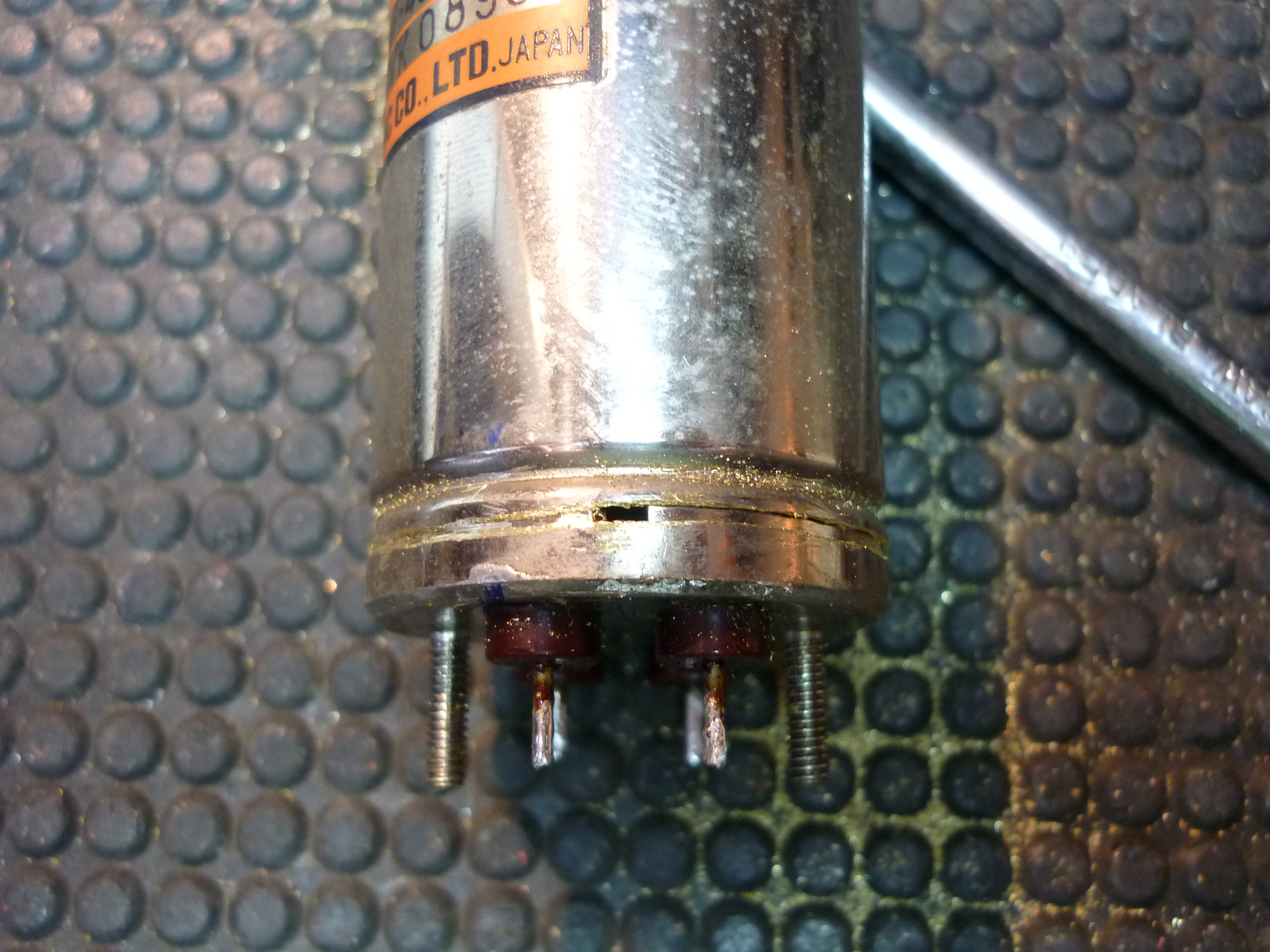
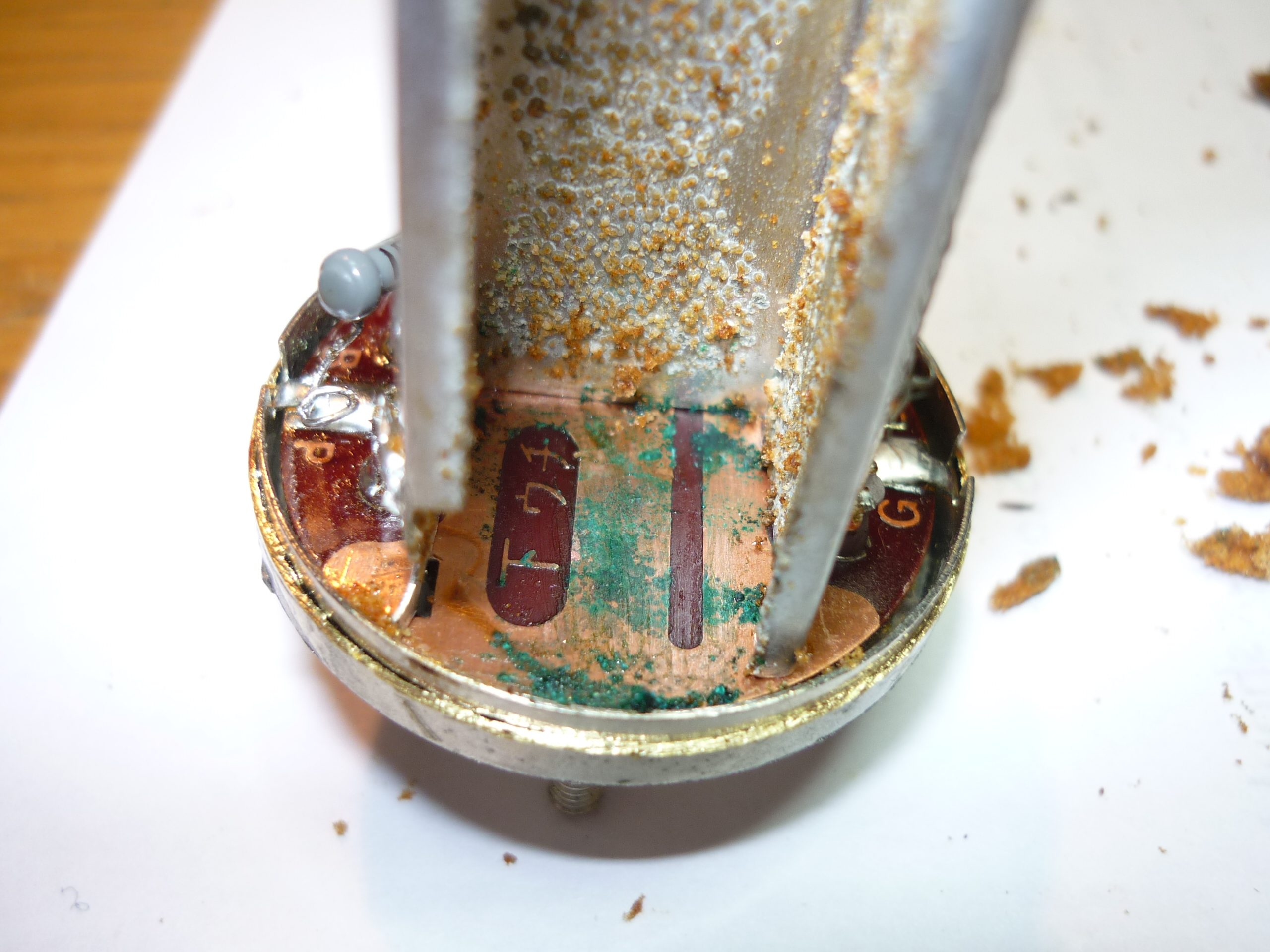
3. Removing the filter cover. There are at least 4 different methods of removing the filter cover (i) cutting the metal using a hacksaw (ii) cutting the metal using a scalpel (Andy G3UEQ) (I misunderstood this method I think - the scalpel is inserted at the bottom end of the filter, to slowly cut through the thin layer of solder, allowing you to remove the filter cover intact) (iii) desoldering with a high-power iron and solder sucker moving slowly around the base (Graham G4EUK) and (iv) desoldering using 3 turns of thick copper wire wrapped around the base, with a gas torch heating the twisted-together ends of the copper wire (indirect heating, hence avoiding overheating the filter) (Ian G3WXG). I opted for the 'sawing the cover off' option, which sounds drastic but is possibly less damaging to the filter than the amounts of heat required to desolder the filter can from the base. Using a Junior hacksaw with the finest-toothed blade I could find, I patiently sawed a shallow ring around the base of the filter - about 3-4 mm up from the bottom of the can - just above midway between the bottom and the annular notch in the can. (According to reports, the solder only extends 1-2mm underneath the can) Continue carefully sawing around this ring and eventually you will see the shiny top of the metal base appearing - see photo below. Continue around the ring, taking care not to saw into the base metal if possible, until the can of the filter is free and can be removed. Lift the can off carefully and be prepared for a horrible sight! In my case, the resonator stack seemed to be completely 'loose' inside the filter, with only the 4 thin wires and the degraded foam supporting it - I was surprised that it had not broken free. You may be unlucky and see damage that cannot be repaired at this stage. See photos below :

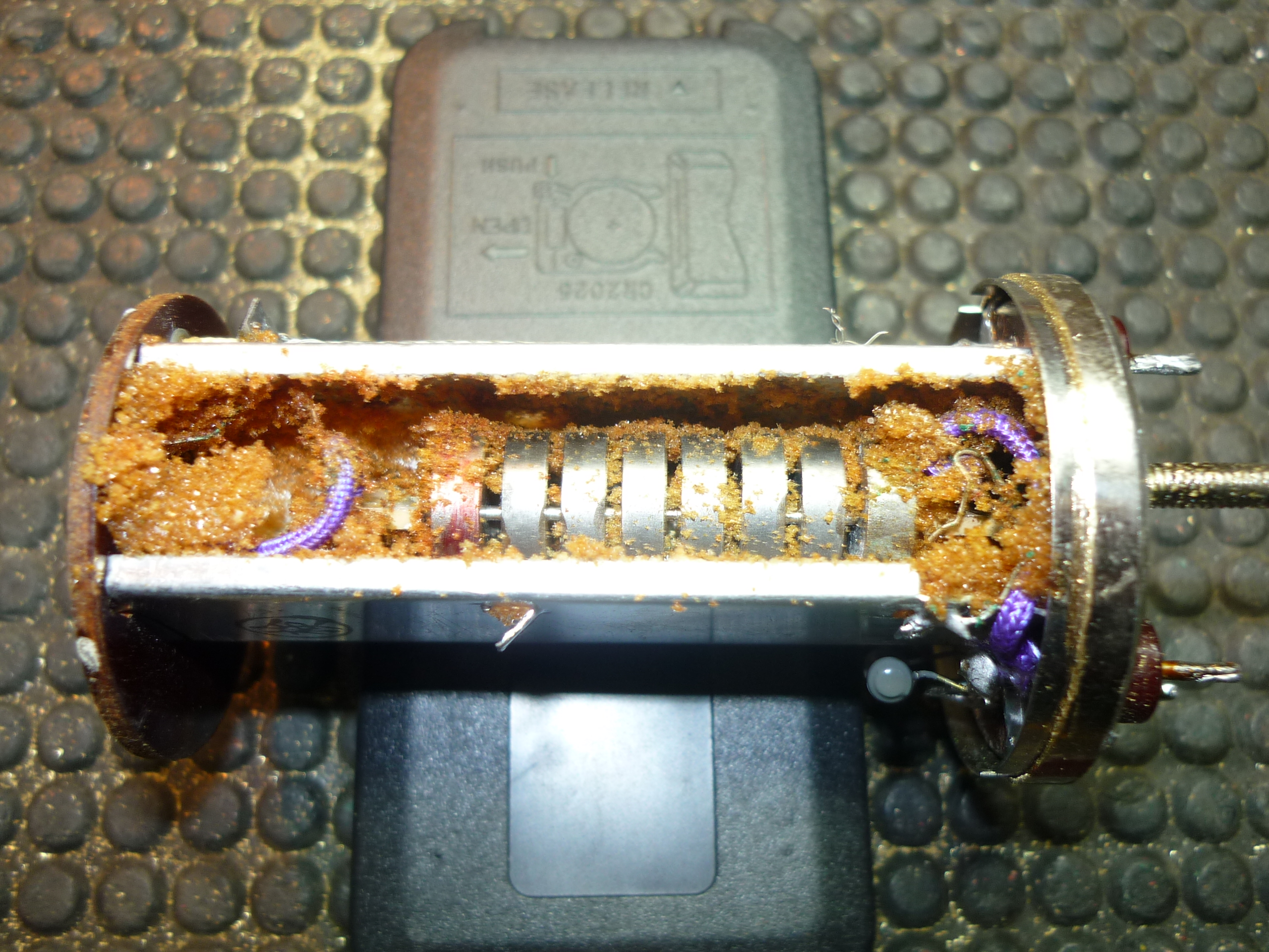
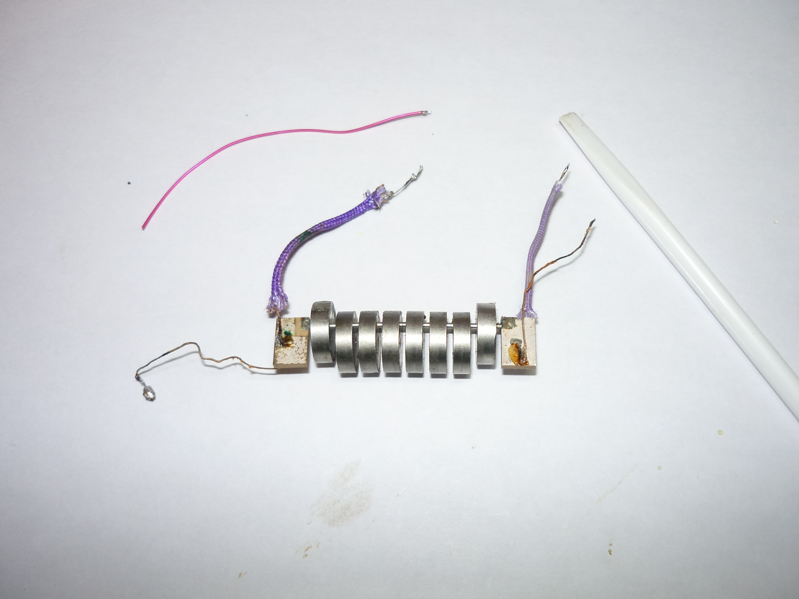
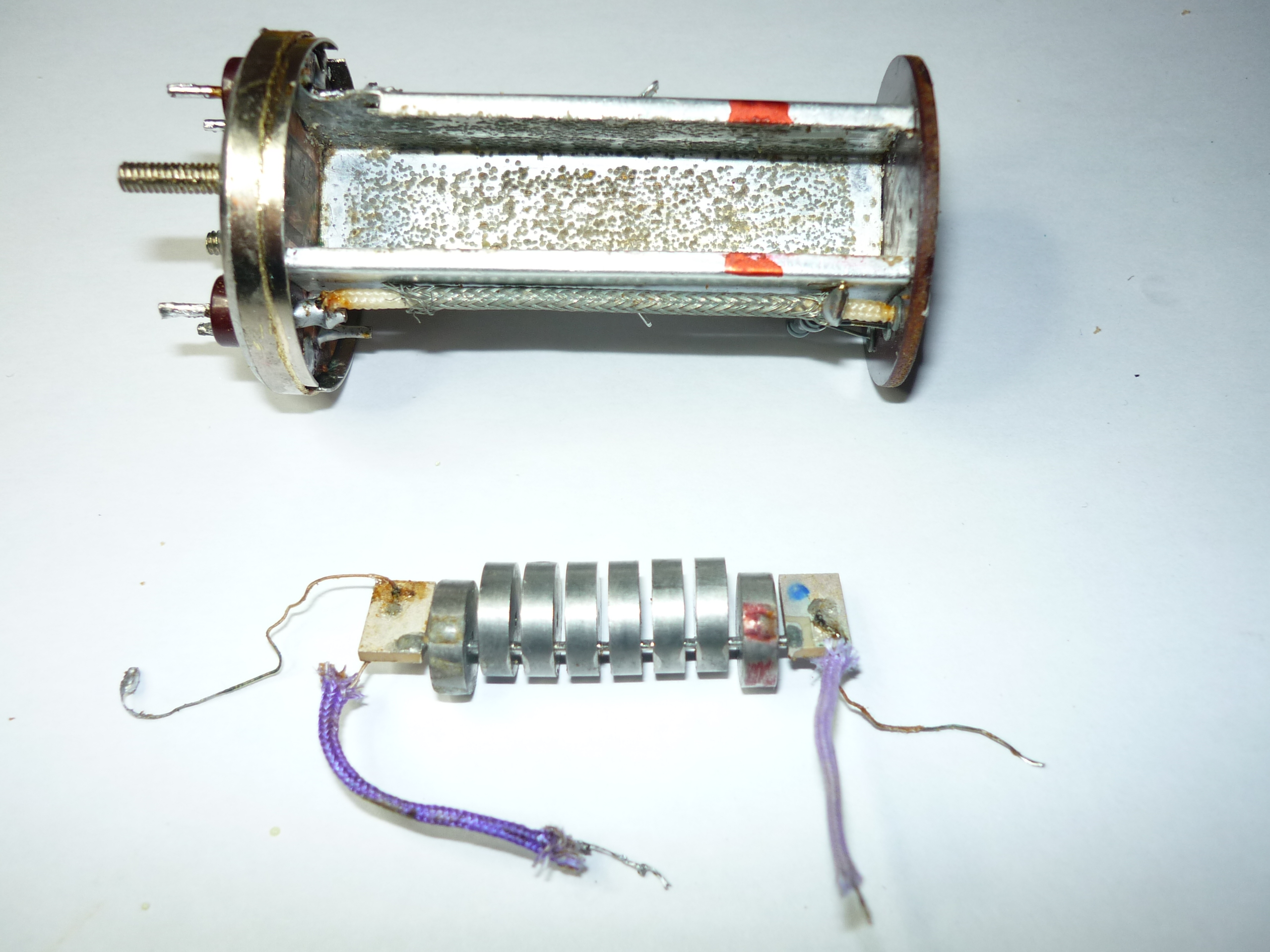
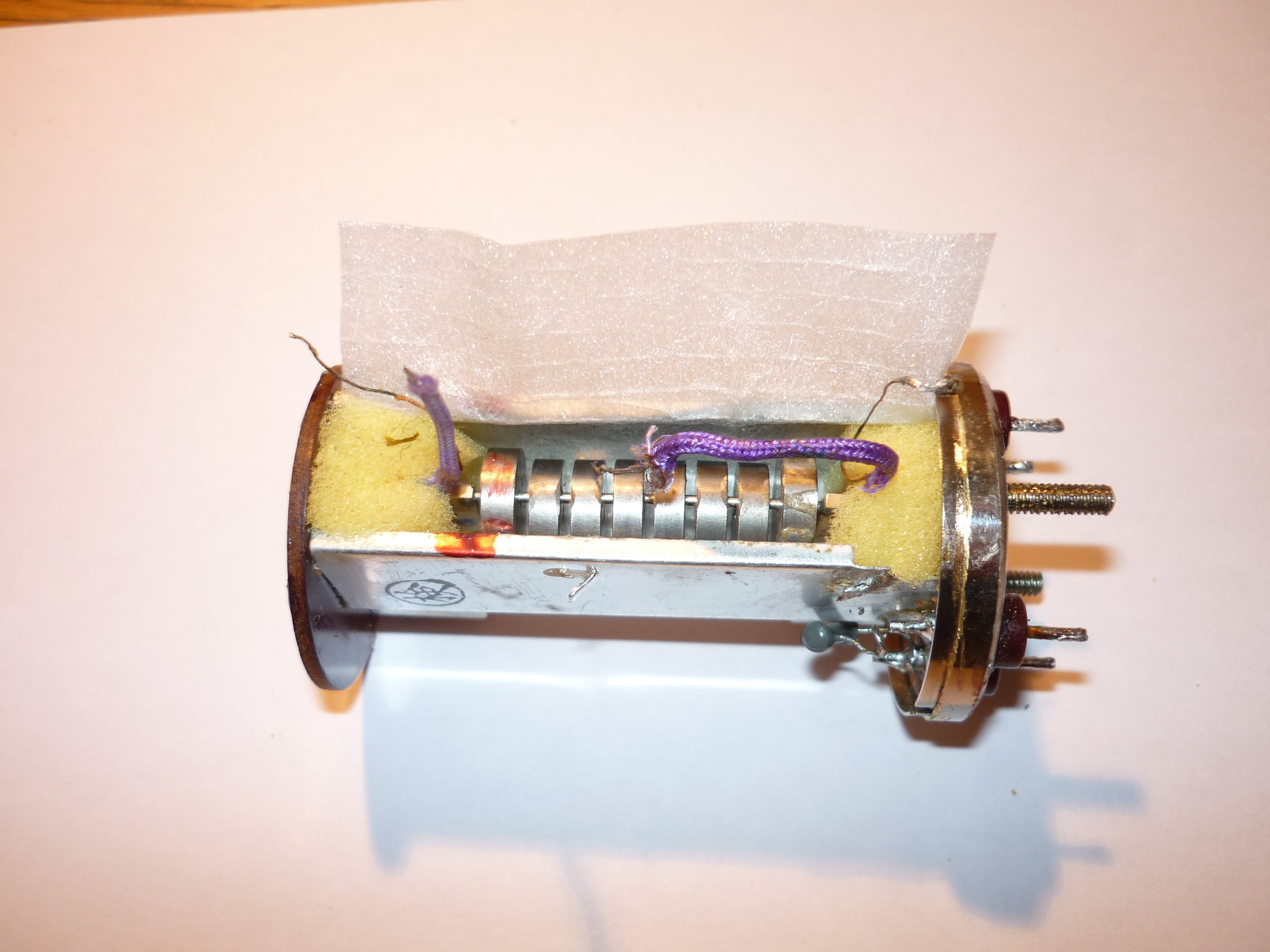
4. Removing the resonator stack from the casing. This requires great care - there are a number of things that could be damaged irreparably. From now on, I worked on sheets of white A4 paper, to ensure a clean surface and so that I could see things easily. I used a bench magnifier which is essential for this job. Firstly, * make sure you note which way around the resonator stack is installed * - this one had a red mark on it, so I marked the casing with a red permanent marker at that end. You have to desolder the 4 wires (2 from each end of the resonator stack) where they are joined to the filter body. Do not attempt to desolder them from the 2 silvered 'flags' at each end of the resonator stack. At the lower end of the filter, one bare wire is joined to the tin-plated brass casing (earth) and the other wire (which is covered in mauve woven sleeving) is soldered to the P terminal, along with one end of a 15kohm resistor. At the upper end of the filter, one bare wire passes through the PCB and is soldered (earth) and the other wire (which is covered in mauve woven sleeving) also passes through the PCB, is soldered to the PCB and connects (via coax) down to the G terminal. Carefully lift the resonator stack out from the filter casing - I used plastic tweezers. In my case, the resonator stack consists of 8 discs, each 10.2mm in diameter, with single interconnecting rods. The discs at each end are offset slightly from the others. See photos below :
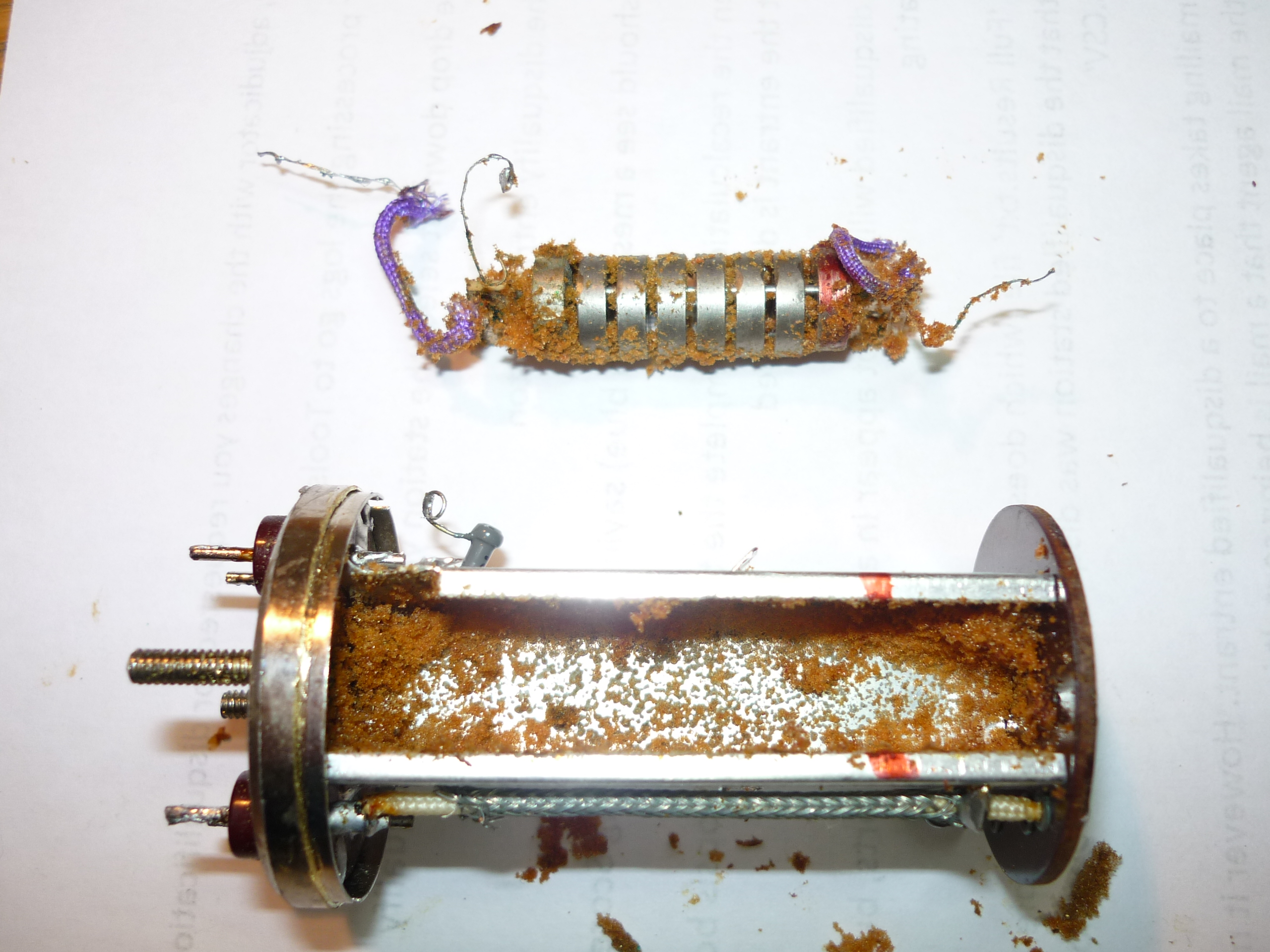

5. Cleaning the components. This requires great care and patience. The degraded foam which was inserted into the filter all these years ago is now a sticky mess which is difficult to remove. Using the inside of the casing as a safe test area, I tried Meths, White Spirit, Nail varnish remover (Acetone) and IPA solvent. None of them worked particularly well, with the nail-varnish remover probably the best. (I briefly considered using some EGR cleaner I have in my garage, but that is a serious chemical!) I found that the filter cover and the filter casing were best cleaned by a combination of scraping with a blunt screwdriver tip and cotton buds soaked in nail varnish remover. You can see from the middle photo above that the disintegrating foam has slightly damaged the inside surface of the tinplate casing - I did not think this mattered too much, as long as no pieces of loose foam were left inside the casing.
Cleaning the resonator stack is the most crucial part of this whole repair. Firstly I gently removed the sticky foam from around the 4 places where the thin wires are bonded (soldered I think) to the end 'flags'. There was some residue of adhesive there - presumably during manufacture they use a small amount to fix the thin wires to the flags after soldering. I then put a small drop of clear adhesive over each wire, about 2mm from the solder joint and onto the silvered surface of the flag, to give them extra mechanical support when I was cleaning the resonator stack. I left this adhesive to harden overnight. (One of the wires did actually break off, but was easily resoldered to the flag using the minimum of heat and maximum speed) These 4 wires are made up of about 5 strands of very thin enamelled wire, so are unlikely to break due to flexing, but where they are joined to the 'flags' they are vulnerable. I next used a combination of plastic 'pick' tools (as used in mobile phone repairs) to physically remove the larger parts of the foam, then a thin cloth soaked in nail-varnish remover, around the thin brass tip of a trimming tool to clean *very carefully* between the resonator discs. Cleaning took about 2 hours in total, to make sure every tiny bit of the old foam was removed. I also removed (with a screwdriver tip) the verdigris that can be seen in the middle photo above, which had slightly corroded the PCB. See photos below :
6. Reassembling the filter. At this stage I was puzzled - what job did the original manufacturer's foam do? It seemed to have surrounded the resonator stack completely, but had it actually been in contact with the discs? I found an online PDF datasheet about this Kokusai filter which shows the internal circuitry clearly, but does not give any details of the internal mechanical mounting arrangements. Online articles suggest using cotton wool or tissue paper to replace the original foam, but I decided on a different approach - my thinking being that if this is a 'mechanical' filter, it would seem logical that the 'mechanical' part i.e. the resonator stack, should not touch anything if possible. This may be un-necessary caution on my part (or my failure to understand how this filter actually works)- time will tell.
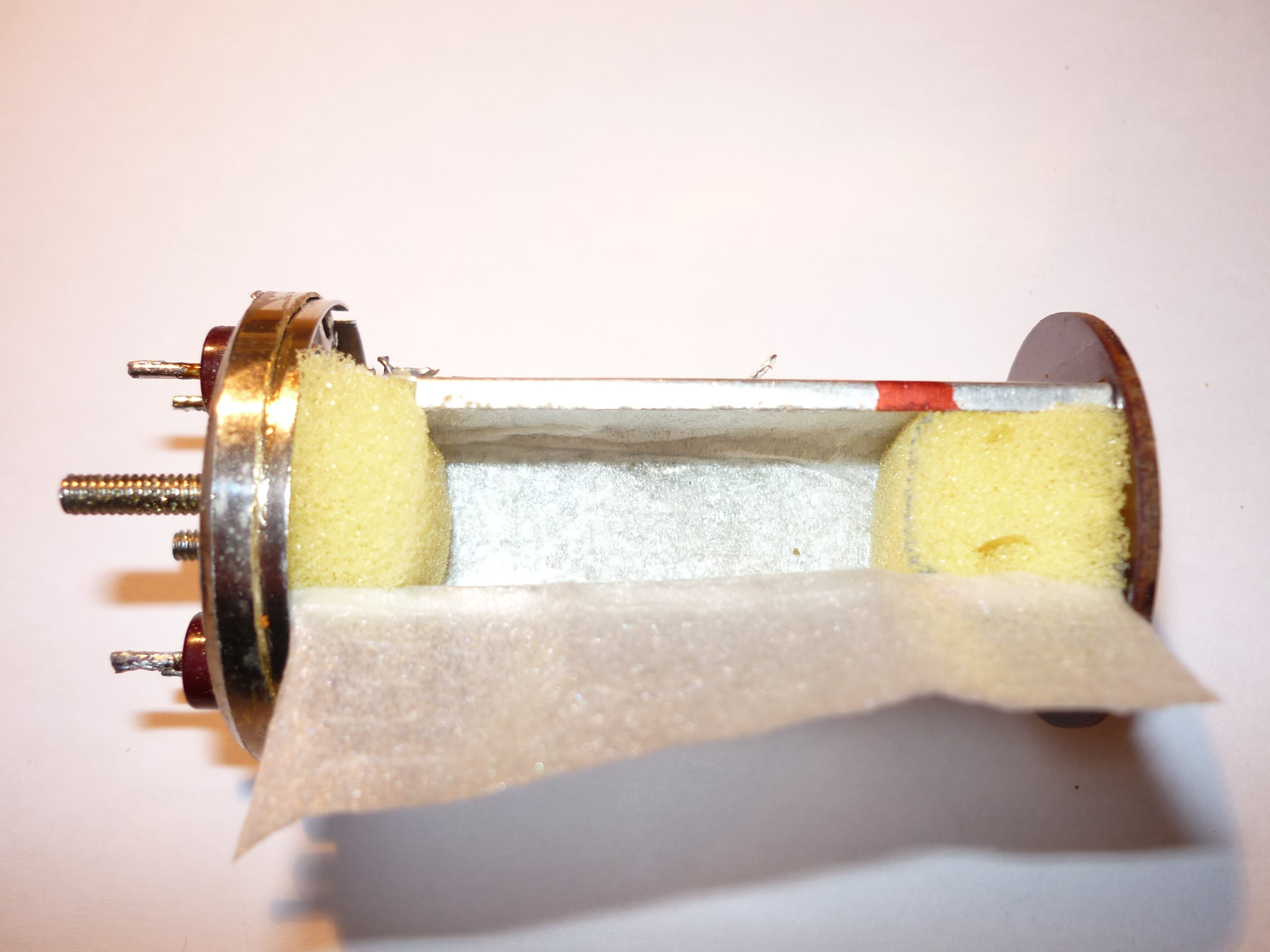
The first step was to glue (using the minimum amount of clear adhesive) a thin 'liner' into the filter casing. (Online info about the newer 'cuboid' style of Kokusai filter indicates that they had a thin cardboard lining) I used very thin (about 1mm) packaging foam to make this liner. Next, using some new foam from a car washing sponge, I used a hot-wire cutter to make 2 small pieces - each 15 x 15 x 10mm approx. These pieces were then fitted into the ends of the tin-plate filter casing, to support the end 'flags' of the resonator stack. The resonator stack is 42.2mm long and the casing is 56.5mm long on the inside, so two 10mm thick pieces of foam grip the end flags securely. I left a flap on the thin lining foam, to cover the open edge of the filter casing once the resonator stack had been re-installed. Place the resonator stack into its new foam end-supports, gently using a small screwdriver to position the ends so the none of the discs are touching anything. See photos below :
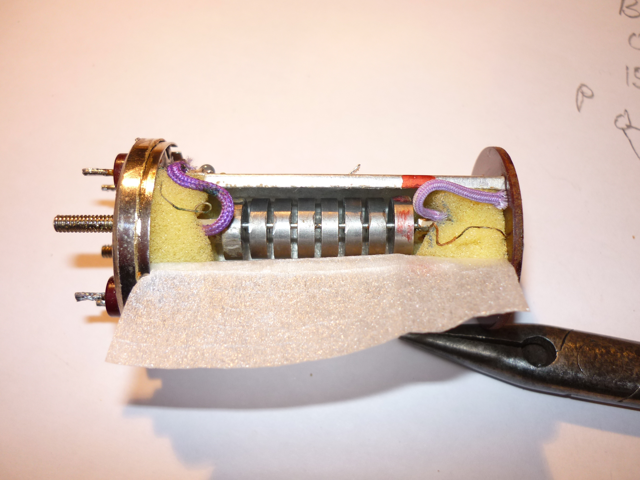
Make sure you mount the resonator stack the correct way around (see red marks) then carefully solder the 4 thin wires back to where they came from (including the end of the 15k resistor) Make sure that the wires are properly separated at the ends nearest to the flags. After a final visual inspection, fold the flap of thin foam over the top and slide the metal cover back onto the filter - make sure it goes all the way on, with only a tiny gap where you sawed through it at the start of the repair. See photo below :
In case of problems which would require another dismantling, I opted to just 'tack' solder the case joint in 2 diametrically opposite places. I will probably solder right around the gap, once I am sure that the repair is a lasting one, to avoid any RF leakage.
7. Reinstallation and testing. I mounted the repaired filter in place using the 2 fixing nuts, but without the screen initially - this made resoldering the connections to the 4 pins easier. After soldering, I removed the nuts then installed the screen.
Switched on - hooray - all seems to be working - the RX is now back to almost full sensitivity and the TX drive seems good. Tuning across a carrier indicates a reasonable filter shape factor. There are still a number of other faults in the radio to follow up, but hopefully the Kokusai filter is now repaired - I will measure the insertion loss once I have fixed the other faults. However, I will treat this transceiver more carefully when moving it around, remembering how fragile the Kokusai filter is internally !
[If the repaired Kokusai filter does not continue to work well, there are other options e.g. make your own xtal filter (5-pole centred on 455.0kHz) but given the cost of having xtals in this frequency range made, a better option would probably be to buy an old Yaesu SSB filter (455kHz 2.0kHz) or even a new INRAD one. You would have to cater for the HT passing through a xfmr at one end of the filter of course]
I hope you find this article useful, especially if you are going to carry out the repair yourself. 73 Chris 12/2/2016