THE G8OSN DF ANTENNA |
|||||||||||||||||||||||||||||||||||||||||||||||||
By Brian
Reay, G8OSN |
|||||||||||||||||||||||||||||||||||||||||||||||||
Introduction The summer months often bring out the urge for some outdoor radio activity, such as Direction Finding (DF or Fox) hunts. Newcomers to DF Hunts usually lack a basic antenna to participate so the G8OSN DF antenna was specially designed to be a good first antenna for those who have yet to try their hand at a DF hunt. No claim is made as to the originality of the basic design, which is a ‘close spaced’ 3 element Yagi, widely used before, most notably in the famous WB2HOL tape measure design. However, the G8OSN version has been engineered to meet several key design objectives: easy to build, using readily available & inexpensive materials, and providing adequate performance- even if no test equipment is available for ‘setting up’. The conventional wisdom is that the ideal DF antenna has a deep ‘null’ which is used to identify the direction to the ‘fox’ by finding a minimum signal or ‘nulling it out’. In the correct circumstances this is probably the best technique but, in less than ideal conditions or in the case of an inexperienced user, the nulling technique is difficult to use. The G8OSN DF antenna has a deep null for use by more experienced hunters and when conditions permit but gives good useable performance in the forward or ‘maximum smoke’ mode- especially if used with a suitable attenuator (see references). The idealised radiation pattern for a typical close spaced 3 element Yagi is shown below: |
|||||||||||||||||||||||||||||||||||||||||||||||||
 |
|||||||||||||||||||||||||||||||||||||||||||||||||
Materials needed- About 800mm of 20mm thin walled electrical conduit (from ‘The Lampost’ at 102 Watling Street) - About 800 mm of 17mm wooden dowel which should be a snug fit inside the conduit (B&Q- should be a snug fit in the conduit) OR about 3 plastic wine corks (eg from one of the excellent Gallo Brothers Wine!) - T piece junction for conduit- NOT the circular type (from ‘The Lampost’) - 2 4 way junction boxes CIRCULAR type, for the conduit (from ‘The Lampost’). - About 2 metres of 50 ohm coax with a plug to fit your radio at one end (Maplins) - About 150mm of 1.5 mm tinned copper wire (Maplins) - 5 x 3 ft or 3 x 1 metre lengths of either 5mm aluminium welding rod or 6mm aluminium tube (the cheap non anodised stuff from B&Q @ �1.46 / length) - 3 sections of electrical 60 Amp ‘chocolate block’, large enough to fit over the aluminium. Ideally get the type that has silver metal inserts rather than brass coloured. (�2.75 from The Lampost’ ) - Insulating tape, 2 solder tags, 2 replacement screws to fit the chocolate block, 2 washers for same, WD40, possibly some Araldite.
|
|||||||||||||||||||||||||||||||||||||||||||||||||
Assembly InstructionsStart by cutting the conduit, dowel and aluminium to length as follows: |
|||||||||||||||||||||||||||||||||||||||||||||||||
|
|||||||||||||||||||||||||||||||||||||||||||||||||
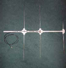
If you are using dowel insulators, assemble them by hammering the 6 short lengths of dowel into the 6 short lengths of conduit, having first lubricated the inside of the conduit with WD40, if required. Rest the conduit on some scrap wood and use another piece of scrap wood to stop the hammer damaging the dowel. Next carefully drill each insulator through the centre length ways to suit the aluminium rod (6mm for B&Q tube or 5 mm for welding rod). Be sure to hold the insulator in a vice or “Workmate” and take care. Push 2 insulators into each of the 4 way junction boxes at opposite ‘arms’ and 2 into the ‘cross piece’ of the T. If you are using wine corks, push them into the junction boxes then drill them - no need for the short lengths of conduit. Assemble the handle, front, and rear spacers by hammering the dowel into the conduit as for the insulators. Assemble the boom as per the photograph below, ensuring the front and rear spacers are in the correct position. File a small groove for the coax to exit the junction box as in driven element-detailed photograph. |
|||||||||||||||||||||||||||||||||||||||||||||||||
| The overall
construction of the G8OSN DF Antenna is shown |
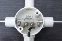
Centre of Driven Element Detail: |
||||||||||||||||||||||||||||||||||||||||||||||||
 |
 |
||||||||||||||||||||||||||||||||||||||||||||||||
The director (front element) is simply pushed through the T piece (it should be a snug fit) and adjusted so equal lengths protrude at each side. If the fit is slack, use some epoxy (e.g. Araldite) to secure it. The reflector is assembled in a similar manner the rods being joined using one of the metal inserts from the chocolate block. Adjust for an overall length of 1050mm and secure with Araldite, if required, after ensuring that equal lengths protrude at each side. The driven (centre) element connection is shown in the photograph above and uses 2 metal inserts and one plastic section of the chocolate block with the little ‘tubes’ the screws pass through cut off. Include a small piece of plastic (from anything to hand) between the inserts to ensure they cannot touch inside the plastic section. Replace the two inner screws on the metal inserts with pan or cheese head screws. Assemble the driven element as shown, adjusting the overall length to 960 mm, with equal lengths protruding at each side and the above assembly central in the junction box. Do not glue at this stage if you have access to an antenna analyser, otherwise glue the elements with Araldite if they are not a snug fit. When assembled the reflector (back element) to driven spacing should be 205mm and driven to director (front element) spacing should be 315mm. If not, check spacers are pushed fully home. Connect the coax (with a suitable plug for your radio) and the loading coil, which is 5 turns of 1.5mm tinned copper wire, 6mm in internal diameter and 20mm long, as per the photograph and secure the coax along the boom with insulating tape. If you have no test equipment simply try the antenna in the open using a moderate signal as a source. You should see a broadish ‘peak’ when the antenna is pointed at the distant signal source and (if you are careful) a deep null if you hold the antenna above you head with the handle pointing at the signal source (still holding the antenna by the handle). Finally, fit the covers to the junction boxes. If you have access to a SWR meter, check the SWR and adjust the coil (by squeezing or stretching it) for minimum SWR at 145Mhz. You should be able to get down to less than 1.5 across the whole of 2m. Finally, fit the covers to the junction boxes. With an antenna analyser set up can be even more precise. First adjust the driven element for over all length for minimum SWR at 145MHz by sliding the elements in and out of the connection point working 1mm at a time equally on each side, then glue the driven elements if they are not a snug fit. Then adjust the loading coil for minimum SWR across the whole of 2m. Finally, fit the covers to the junction boxes. Note: my design proving prototypes had a 1.5 SWR bandwidth of over +/- 2 MHz centred on 145MHz WITHOUT adjustment, using the dimensions given so do not worry about setting up if you don’t have access to test equipment. |
|||||||||||||||||||||||||||||||||||||||||||||||||
HAPPY FOX HUNTING |
|||||||||||||||||||||||||||||||||||||||||||||||||
References: The WB2HOL tape measure version can be found at: http://home.att.net/~jleggio/projects/rdf/tape_bm.htm A suitable simple passive attenuator, to assist when the source signal is too strong, can be found at: http://home.att.net/~jleggio/projects/rdf/p_atten.htm
|
|||||||||||||||||||||||||||||||||||||||||||||||||