The Phoenix 4m Dipole |
|||||||||
By Brian Reay, G8OSN |
|||||||||
IntroductionThis 4m dipole was designed as a club project for the Phoenix Radio Club to use with a bulk purchase of 4m converted "PMR" radios. No claim is made as to the originality of the basic design- a dipole is a dipole- although the design has been engineered for easy assembly and to give repeatable results. The design incorporates a 'sleeve' (or 'bazooka') balun to provide a transition from unbalance coax to the balanced feed point of the dipole. The SWR is <1.5:1 at 70MHz without final adjustment. |
|||||||||
| Materials All the materials used should be readily available, the coax and connectors from normal amateur radio suppliers and the various hardware from the likes of B&Q and electrical shops. The following items are needed: 2 Aluminium tubes 6mm diameter x 1m long (B&Q) 1 Round T plastic 20 mm conduit junction box (B&Q or electrical shop) 1m of 20mm plastic conduit (B&Q or electrical shop) 1 20mm plastic conduit coupler (B&Q or electrical shop) 965mm of 15mm cope pipe (B&Q) 2 sections of 60A electrical 'chocolate block' terminal strip RG213 coax as required for installation plus approx. 1m 2 nylon (or plastic) bushes, approx 20mm in diameter to fit conduit junction box and drilled for 6mm Aluminium tube. Solder tags, pan head screws to fit electrical 'chocolate block' terminal strip, insulating tape, insulated wire, silicon sealant, 'solvent weld'.
|
|||||||||
| BALUN
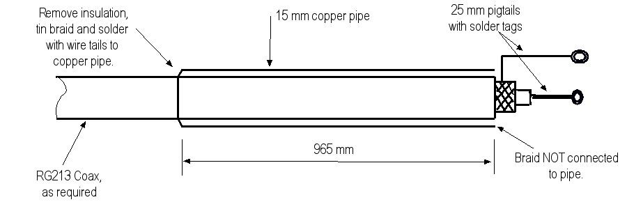
Construction Ensure that all burrs and 'whiskers' are remove from the ends of the copper pipe and 'tin' the outside of the pipe at one end.
Feed the coax through the copper pipe until the insulated junction of the coax and pigtails is flush with the UNTINNED end of the copper pipe. Using a scalpel or Stanley knife, remove a 5mm wide ring of the coax jacket where the coax emerges from the tinned end of the copper pipe. Tin the exposed braid of the coax with a hot iron and solder 2 or 3 short pig tails from the exposed braid to the copper pipe. This junction is covered in insulating tape. The balun assembly should look like this (note: insulation tape at junction of coax to pipe and coax to the pig tails not shown) :
The balun assembly is next enclosed in plastic conduit which has the conduit coupler the end covering the solder joint between the coax braid and copper pipe. Ensure you have protected the areas detailed above with insulating tape! The length of plastic conduit is adjusted so that it is flush with the junction of the coax and 25mm pig tails.
|
|||||||||
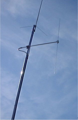
| Dipole
Assembly
|
|||||||||
Testing and AdjustmentFit a suitable coaxial plug to suite your installation and install the antenna in its final location. If this is on a metal mast, ensure that the dipole elements are around 90cm from the mast. (For those unfamiliar with antenna mounting, low separation is widely used in professional low band applications. Equally, if the mast isn't metal, the spacing can be varied to suit the installation.) Check the SWR, which should be <1.5:1. If not you can trim the elements slightly (5mm at a time and ensuring you remove equal amounts from each element). There is little to be gained by repeated adjustments once you have a match that is better than 1.3:1 (there is always a danger you might trim off too much!). Finally, seal the ends of the elements with small screws secured with epoxy resin.
|
|||||||||