Following recent discussions with local stations about "quiet" receiving antennas for 160m, I dug out a small multi-turn which I'd built some years ago. This is a half-size copy of one which I made for Clive M0VCF to use at his QTH in Bristol (with a switching-unit to select a separate transmit antenna).
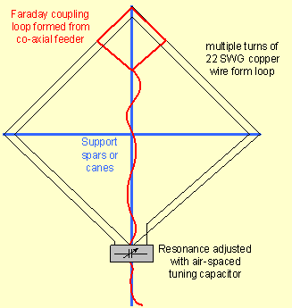
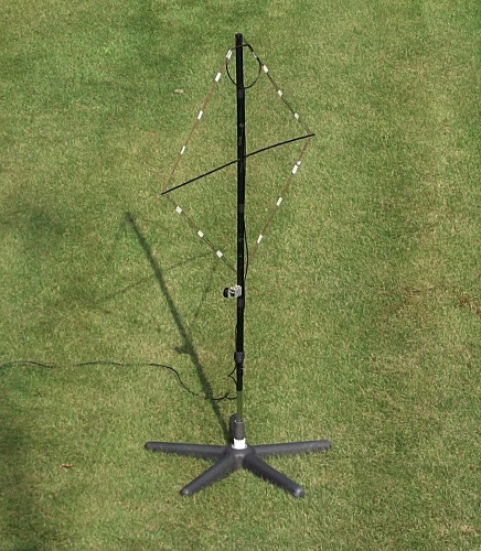
This is a simple square loop, with four turns supported by the ends of a couple of fibre-glass kite-spars, and tuned with the air-spaced tuning capacitor from an old LW/MW radio. I'd managed to arrange the resonance so that with the capacitor fully-meshed it tuned 160m, and with it almost unmeshed it covered the 80m band.
The low-impedance co-axial connection to the receiver was via a standard "Faraday-coupling" loop.
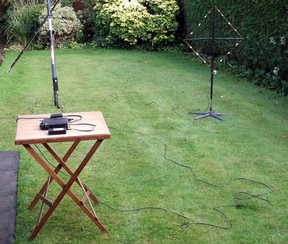
During a local net on 1.953kHz in September 2016, I set this up on the lawn and compared the signals with those from my adjacent top-loaded inverted-L antenna. I had taken down the vertical whilst I tested the loop.
When listening on my vertical TX antenna, I use the Attenuator in my radio, so that the general noise-floor sometimes goes down to "S0", whilst the local stations are still S7 to S9+.
Then using the little loop (now with the RF & IF gains turned up full) the noise-floor still didn't register on my meter and those same stations were showing S7 to S9, but the signal/noise ratio did sound noticeably better. This suggested that the underlying noise-floor was well "below S0", which is perhaps not surprising on a loop of this size. I didn't do any tests with rotating the loop, but I had initially set it up in the lowest-noise orientation (which turned out to be with the loop parallel to the line of the houses).
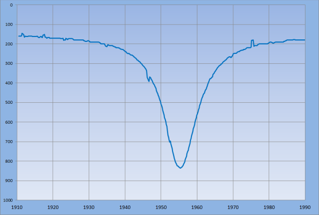
A swept-frequency plot shows just how tight its resonance is (the frequency axis is 10kHz per division).
Having seen how effective this antenna can be in improving the SNR on receive, I wanted to be able to switch it in automatically.
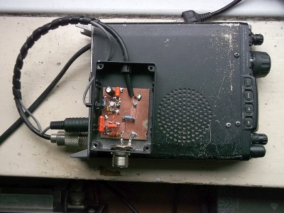
So I've now devised a circuit to do this, operated from the "ACC" socket on the back of a Yaesu FT8x7 transceiver.
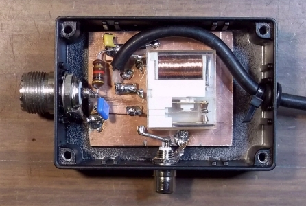
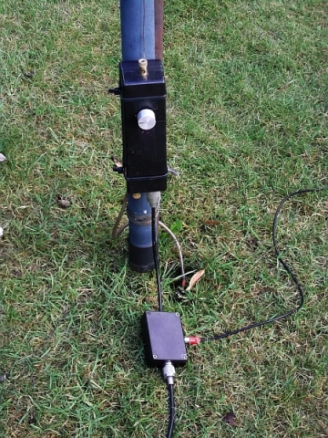
This 8-pin mini-DIN socket includes Vcc ("13.8V") and PTT ("TX GND") outputs, which I've used with a transistor switch to control a DC voltage fed through a bias-tee onto the antenna-feeder. When the radio is in receive, this closes the remote change-over switch to select my tuned-loop antenna (see above), and when I go over to transmit this voltage falls to zero, so the relay drops back to selecting my default Tx antenna (the top-loaded inverted-L). I did it this way around so that there's no danger of transmitting into the receive loop if I forget to connect up the control-box at the transceiver end (and this supply could also be used to power up an active Rx antenna).
The pictures below show the transceiver-end and antenna-end units and the complete system on test in my garden.