QRP 'HF' SWR METER


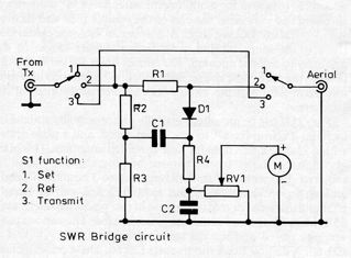
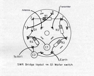
                       R1,R2,R3 = 51  ohm 2 watt non inductive. 
                       R4       = 1K  ohm 2 watt.
                       RV1      = 10K ohm linear control or pre-set control.
                       D1       = OA91 type diode.
                       C1       = 0.001 uF ceramic disc.
                       C2       = 0.01 uF ceramic disc. 
                       S1       = 4-pole 3-way switch ( Maplins)
                       Meter    = 1Ma or less.
                       2          SO239 antenna sockets.
                       Suitable metal box or case.


Total cost of parts from maplins.


CONSTRUCTION.

This swr meter has apeared in many Radio magazines including Short wave mag,Practical Wireless, Radcom etc.
It is an easy project to build with no coils to wind,Resulting in an swr meter that is not frequency critical.Most if
not all The components are easy to obtain from Maplins.Only 1 watt or so of forward power is required to check
your antenna swr. The meter MUST be switched out of circuit after swr check's before transmitting as power in
excess of 2 watts will damage the components and meter.R1,R2,R3 must be 2 watt non wire wound R4 can be
a half watt resistor of any type RV1 is a carbon pre-set or standard control which can be either preset or brought
through the box front panel as a calibration control. C1 & C2 are disc ceramic type capacitors with a reasonable
maximum working voltage (250v) or more, I used 1kv types simply because I have some in my junk box.

CALIBRATION.

Connect your transmitter output to the meter switch to position 1 (set) and feed between one & two watts or so
into it then adjust the meter to read full scale with RV1.Next switch to position 2 (ref) and connect various value
resistors between 50 and 400 ohms(non inductive carbon or carbon film )types one at a time across the antenna
- socket and note the meter readings for each,This simulates connecting antenna's of differing impedence's with
the 50 ohm ('resistor/antenna')giving the lowest reading (1:1 swr)and 400 ohm ('resistor/antenna') the highest -
(8:1 swr)DON'T EXCEED 2 WATTS INPUT as this may damage the components.remember to switch to
position 3 (transmit) before transmitting.


THIS METER IS NOT SUITABLE FOR VHF OR HIGHER FREQUENCIES.