TVI. FILTERS.
diagrams and photo's by g4wpw
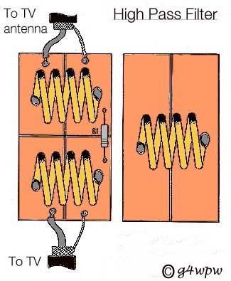
The High pass filter is for insertion into the lead from the TV antenna to the TV,
The insertion loss of this filter is very low,it is of the ( braid breaker ) type
for HF and VHF/UHF frequencies.
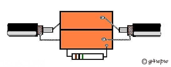
The Filter comprises of a 1 inch by 2 inch double sided copper clad printed circuit
board,The Upper side of the board has a " cross " pattern cut into the copper and
the underside has a single cut lengthways as seen on the diagrams.
The 3 coils consist of 4 turns of 18 swg enamel wire a quarter of an inch in
diameter spread to half inch length,2 soldered on the upper side of the board and
the remaining coil soldered on the underside.
R1 is a 1meg ohm or above 1/4 watt resistor soldered as shown this is the static
discharge path.( I used a 4.7 meg ohm.)
2 short lengths of TV antenna cable ( about 6 inches each ) are connected as shown
to the upper side of the board ( the braids are on the same side and the center core's
are on the same side THIS IS IMPORTANT )
TV antenna coaxial male plug can be fitted on the end of one cable and a female plug
to the end of the other cable this makes connection and removal easy.
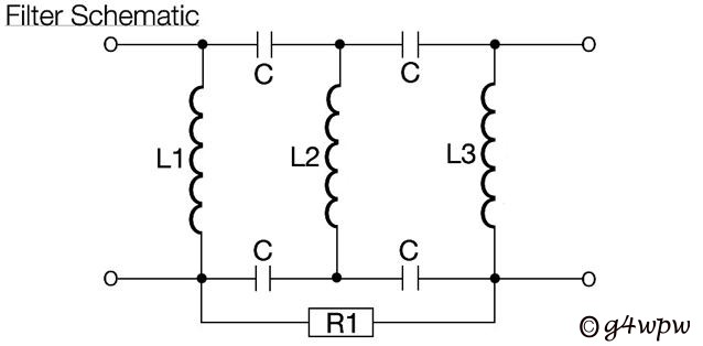
L1 and L3 are on the upper side of the board L2 on the underside C is the
capacitance of the copper "plate's" between both sides of the board approx 2pf
for each capacitor.
BASIC PRINCIPLE'S
This combined braid-breaker and high pass filter prevents HF signal currents from
flowing down the inner and outer of the TV antenna coax cable.L1,L2,L3 have a low
reactance to HF and VHF signals,thereby by-passing( shorting )the interfering
currents.
The capacitors have high reactance to HF/VHF signals,effectively blocking these
"interfering"signals from the TV receiver.
At the TV receive frequencies the conditions are reversed, the capacitors presenting
a low impeadance path to the TV received signals enabling them to pass,and L1,L2,L3
presents a high impeadance at this frequency thereby having no effect on the received
TV signals.
R1 is for static discharge of the outer screen of the TV antenna coax.
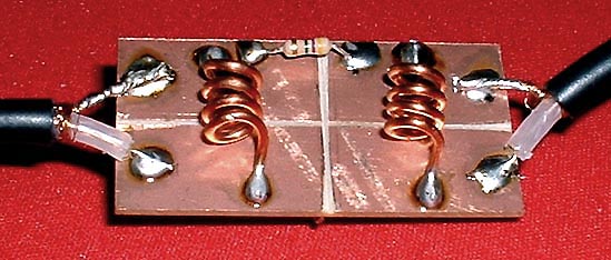
THE FINISHED FILTER.
FARADAY LOOP FILTERS.( Braid Breaker )

The Faraday loop filter comprises of 2 loops of the TV antenna coax 2.5 inch
diameter,tape'd side by side, The TV antenna feeder is cut and each loop is soldered
to its own braid as shown above.The loss on this type of filter is high and should
only be used in a good TV signal area.
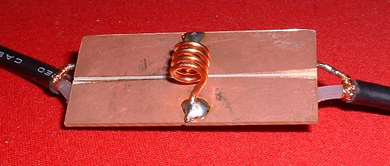
Above is the modern version of the braid breaker type of filter it comprises of a
1 inch square of double side'd copper pcb with a saw cut down the center,the
TV antenna feeder is connected as shown on the above diagram,the board is cut the
same on both sides,and the coax connections are the same on both sides I have found
the insertion loss to be much lower than the Faraday loop. it is also a good idear
to fit a 1 meg ohm resistor between both braid connections of the pcb as a static
discharge path.AS WITH THE FIRST FILTER A COIL CAN ALSO BE ADDED ON EITHER SIDE

THE FINISHED FILTER.