1090 MHZ AERIAL
![]()
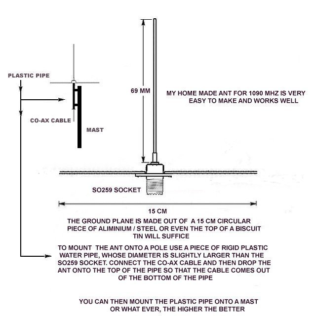
The measurements are not absolutely critical but stick to them as close as possible
![]()
![]()
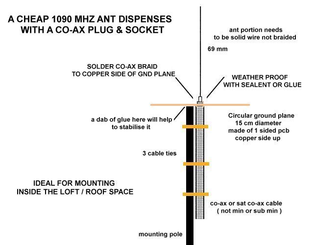
SIMPLE 1090 MHZ ANTENNA WHICH
WORKS VERY WELL

![]()
You can use one of the cheap r.f amplifiers like the one below, make sure its suitable for use at 1090 MHZ

![]()
If you are using the original aerial that came with the rtl dongle for ads-b reception then it is to long, you need to optimise it for 1090 mhz i.e cut it down to about 69 / 70 mm.

![]()
136.963 MHZ VERTICAL DIPOLE
|
|
|


![]()
A SIMPLE J POLE ANT FOR 1090
MHZ
|
|
|
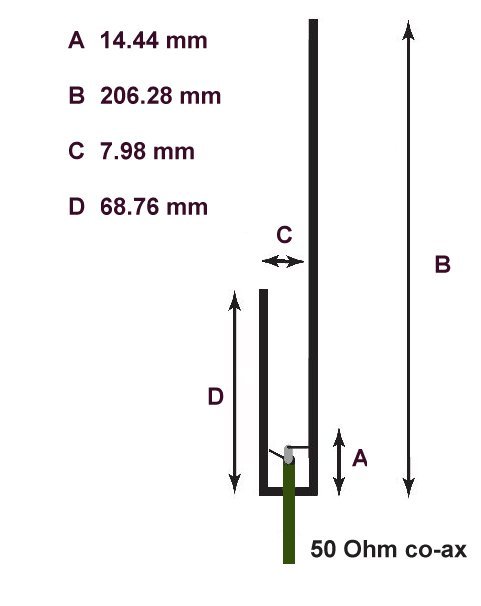

I made it out of 1mm brass tube - I soldered it at the two bottom corners (or you could just try to bend it) it can then be placed inside a piece of plastic tubing
The good thing about this ant is that it does not require a ground plane - place it as high as you can
![]()
SLIM JIM ANT FOR AIS ON 162 MHZ
|
|
I MADE THIS OUT OF COPPER TUBING - ABOUT 2 MM IN DIAMETER - SOLDERED AT ALL OF THE CORNERS AS IT WAS TO FLIMSY TO BEND |
|


![]()
COLLINEAR ANT FOR 1090 MHZ
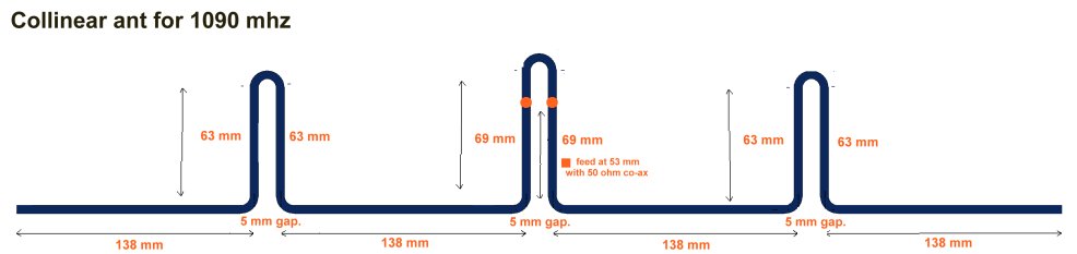
This ant is very cheap and easy to make and performed a lot better than I thought it would - I made it out of enamelled covered copper wire about 2.5 mm thick - not sure what the 'swg ' was
Brass/copper tubing would make it more robust but I think there would be problems with the 'bends' it will tend to flatten out
![]()
MORE SIMPLE COLLINEAR ANT FOR 1090 MHZ

![]()
1090 MHZ QUAD ANTENAE

![]()
A FILTER FOR 1090 MHZ

This filter may help if you have break-through / interference from a nearby transmission - there will be a slight insertion loss - it must be tuned exactly to 1090 MHz - otherwise you will have an un-acceptable insertion loss
![]()
DIPOLE LENGTH CALCULATOR

So you want to make a dipole for the 14 MHz (20 metres) ham radio band?
example - 466 / 14.025 MHz = 33.226 feet - so a 14 MHz ham radio band dipole has a total length of 33 feet - each leg is 33/2 = 16.6 feet
![]()

There are two local oscillators in most lnb's, switched with a 22 khz tone - without the tone a 'universal' lnb will default to the 9.75 g/hz lo - giving a range of 10.7 - 11.7 g/hz - the 22 khz tone should allow it to receive in the 11.7 - 12.75 g/hz range ( using either 12/18 volt supply ) 18 volt supply will also change the polarisation. i have not tried yet to super impose a 22 khz one onto the line as 10.7 - 11.7 g/hz is sufficient range for the 10 g/hz band i am still experimenting with things
* please check your specific lnb to confirm maximum voltages and frequecy range etc *
![]()

![]()


Note the transmissions are RHCP but using the dish above will reverse the polarisation so you must wind the helix so it is LHCP

![]()
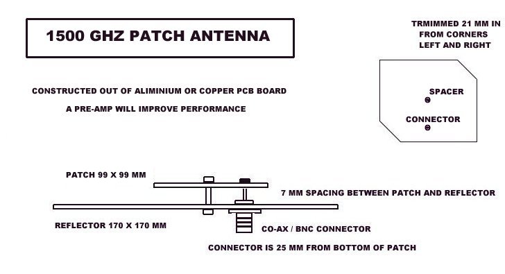
This
patch antenna is based on the design by 9a4qv
note
: the 7 mm spacer not only sets the distance between the patch and the
reflector but also provides earthling ( a build up of static on the patch
during humid weather / thunderstorms could damage your pre-amplifier or dongle
) at the operating frequency of the antenna this metal spacer will appear
as a high impedance and it will not impair the signal
I tested
the antenna in the first instance - to check for shorts etc using a 1090 MHz
signal as it’s a reliable guaranteed signal source - it received planes out to
260 miles on a regular basis ( nooelec lna at the ant and 4 metres of cable feeding to a
nooelec bias tee dongle ) but the antenna is not designed for this frequency or
mode but it does outperform a normal vertical ant - the ant will definitely
work ok on l band signals but it needs the pre-amp and/or a clear view of the satellite
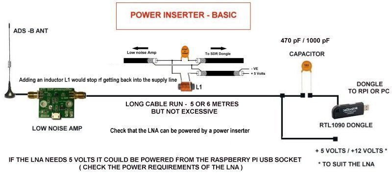
it's important to note that the patch and reflector will present a short cct at the co-ax socket which will cause a problem for a tee bias dongle, in which case replace the metal spacer with a plastic one, the chances of having a build up of static which might damage the dongle, are I would think quite remote anyway
A dc blocker (1000pf capacitor would do) would be needed if you elected to keep the metal spacer or are using a j pole ant or something similar
|
|
|


![]()

![]()
![]()