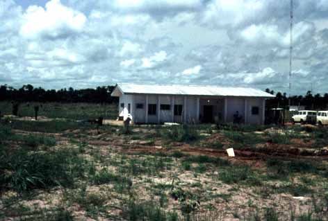
A typical station - this one was the Green Slave at Badagry on the Nigeria Benin Border. The layout of a most Decca Stations followed a standard pattern, and included an "Ops" Room - the main equipment room containing the transmitters, phase control equipment and other technical equipment, a battery room with dual banks of 24 Volt and 110Volt Batteries, the "Power" room, containing the rectifiers/chargers for the batteries and diesel control rack, a store room, two bedrooms, a bathroom - or more correctly just a shower and toilet, a kitchen, and the very important diesel generator room.
Diesel Generators were the sole source of power used for the Nigerian Chains.
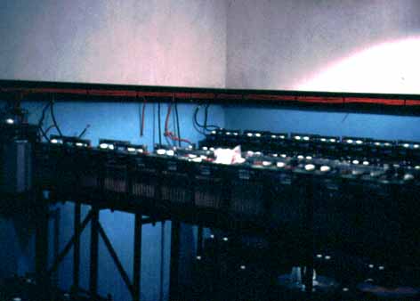
The Battery Room showing the dual banks of 24VDC and 110VDC batteries. The batteries, made by Tungstone, typically had a reserve capacity for 16+ hours full operation in the event of a total diesel failure. Dual banks were used so that a single bank could be switched out of service and given an equalisation charge.
The rectifiers/chargers were in an adjacent room - the "power room" (my picture was too poor to include on this page) and were multiple Kingshill 10A regulated power supplies for the 24V and 110V in parallel arrangements. I think there were 4 in parallel for the 110V supply and 8 in parallel for the 24V system. A separate rectifier was used for the equalisation charge.
Also in the power room was the diesel control cabinet which would monitor the engine parameters while in operation. This could remotely start a diesel upon command from the Master Station or shut down the duty diesel and start another in the event of a detected anomaly.
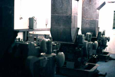
The Lister HR4 4 cylinder air cooled Diesel Generators with ECC three phase brushless alternators running at 1500RPM to provide the 50Hz station supply. Each Engine was fitted with large external lube oil tanks containing about 45 gallons of oil to enable the engine to operate continuously for one month before service, and thus with the three diesels, the station was planned to run three months before a station visit was required.
Fuel was taken directly from the bulk supply tank outside - no day tank was used - and sump floats with cut-off valves where fitted to each engine to shut it down in the event of a fuel leak, and a fire wire shut of the fuel to the entire station in the event of a fire. A Harwood Water Separator was installed at the fuel line entry to the room - but didn't work very well - the pressure of the fuel supply, although only a maximum of about 10ft was too much for it. In fact water in the fuel was not the problem - it was dirt which was so fine it even got through the fuel line filter on the engine and cause a number of injector pumps to cease up.
Three HR4s were used at each station, except for dual stations such as the Lagos Red at Abigi which used the larger 6 cylinder HR6 engine and the monitoring station at Agbowa which used a 2 cylinder ST2. The Diesel Generating Sets were the station's sole power source, with one engine being duty and the other two as standby. Each HR4 set had an output of about 40KVA, and the HR6s had an output of about 60KVA. The building air-conditioners represented the single greatest load, the nominal technical load for the transmitters and other equipment was less than 3KVA.
As under mormal operation, each diesel was likely to sit as a standby unit for two months before becoming the duty unit, to keep the starter batteries charged up on the non duty engines, separate mains powered chargers made by Erskine were installed and were mounted on the rear wall of the room.
The rectangular air ducts rising vertically from the diesel engine was for the exhaust cooling air. The combustion Exhaust systems are behind the ducts and cannot be see in the photo.
The station diesels were your passport to comfortable living whilst "on site" as they provided the essential air-conditioning and also power for cooking. If a diesel stopped for whatever reason, getting the engine restarted or another on-line became the only objective!
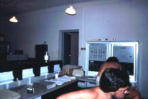
The Master Station Control Desk. The Slave stations were unmanned.
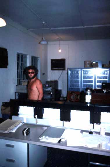
Photo of part of the Control Desk showing the pen recorders with the Transmitters at the back of the room. Also just to the left of the left most transmitter rack was an HF SSB transceiver which was our sole means for inter-station communications and with the office in Ikeja, a suburb to the North of Lagos near the International Airport.
The transceiver was a KW2000CAT made by KW Electronics which at that time was part of the Decca Group. The KW2000CAT was all solid state using Plessey SL600 series ICs with the exception of the driver and PA, the latter being a pair of 6146s. Power for the KW2000CAT was from a noisy 24 VDC transistor inverter running from the 24V station batteries.
Nigeria is located in the Tropics with two distinct seasons, rainy and dry. There was a high incidence of lightning throughout the year, but during the dry season it was particularly spectacular. During this time the evening sky was normally quite clear and cloudless, and in the distance the sky was lit by what seemed constant and massive lightning discharges which almost turned the night into day. I have never experienced such a spectacular show of lightning as I did in Nigeria.
Consequently, the static noise levels made HF virtually unusable at night.
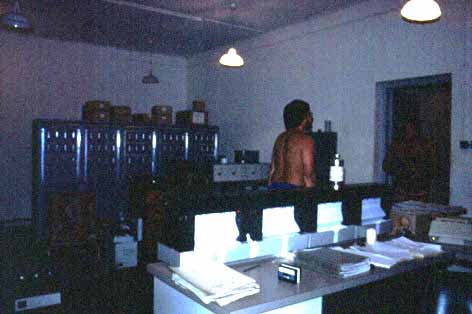
Another view of the five Transmitters at the back of the room and also in the middle distance just visible by the door is the phase control equipment - basically exciters for the transmitters. The transmitters were arranged in order of frequency from left to right, i.e. 5f, 6f, 8f, 8.2f and 9f. Although called transmitters, these were really power amplifiers.
A better view of the Phase Control Rack and the Transmitters at the back. Note these are not the same transmitters featured in the latest edition of the RSGB's LF experimenters manual.
Each Transmitter comprised of 16 modules, 4 modules for the driver and 12 for the main PA.
The four driver modules were located at the top level of the transmitter rack and contained 3 TO-3 silicon transistors in a common base arrangement. The 12 PA modules occupied the lower 3 levels and contained 4 TO-3 transistors, again in a common base configuration. The main Tank circuit was at the very bottom of the rack and was a conventional push pull tuned circuit with link coupling. A selector switch on the tank's front panel allowed section of taps on the output link to vary power level. The nominal output power of each transmitter was 1200 watts into 70 ohms. A fan with dust filter located at the bottom of the modules forced cooling air up through the PA and driver modules. Each transistor had a neon connected between the collector and ground and had a fuse in series with the output bus. This gave a simple visual indication as to the likely health of each transistor in the transmitter. A transmitter test set - which can be seen on top of the left hand transmitter in the photo (with four meters) was used to test and measure the operational parameters of each module. These transmitters, although inefficient by today's standards were extremely reliable and faults were virtually unknown. Power for the transmitters was both 24VDC and 110VDC. Output to the antenna tuning system was via 70 ohm coax which ran to the Antenna Coil House.
Each Phase Control Rack had triplicated control bays. A fourth bay contained a voting system whereby each control bay was compared to the other two to detect a fault - a technique used for very high reliability "fly-by-wire" aircraft systems.
Each Control Bay comprised of:
and
The operation of the control bay was to receive the off-air signal from the APS (Anti Precipitation Static) antennas outside the building and phase lock the divided output 10MHz HP oscillator module to it. The output of the oscillator was then divided in separate chains to provide the outputs to the transmitters. Within these divider chains two variable phase elements were incorporated. The first was adjusted and set during commissioning so that Lane 0, Zone 0 from that Slave station would start at the Master Station (hence avoiding the necessity of having to build the Slave at precisely a whole zone and lane distance from the Master). The second was a continuously variable element to compensate for phase variations due to the antenna coils re-tuning due to changing weather conditions.
The main antenna was the reference point for all phase timings, and three current transformers, one for each control bay, were located at the base of the antenna in the coil house and sampled the radiated signal. This sample which was connected to the phase control rack in the main building via screened "twinax" cable. The top five edgewise meters on centre panel of the phase control rack give a visual indication of the phase error of the 5 transmitted frequencies.
The Phase Control rack at the Master Station was identical to that of the Slaves but with the off-air receiver part was disabled.
During part of the transmission cycle, each station would transmit a "Multipulse" when all 5 frequencies were transmitted simultaneously. Although there were only four stations in a chain, an additional frequency known as the "Orange" or 8.2f was transmitted to give a course zone reading. On the Nigerian Chains, the 8.2f signal was also used for the control and monitoring of the slave stations. The circuits for the 8.2f status transmitter encoder and control receiver decoder was contained in the fourth bay.
This 8.2f signal was BPSK modulated by the phase control rack with a simple (approx. 20 bit) status or in the case of the Master station, a control signal with an extended parity check. Remember, this was before the days of CRC and other error checking and correcting codes. The BPSK modulation was hard keying via an Exclusive OR gate circuit, but the Q of the transmitter PA and the Antenna Tuning Network was used to effectively limit the radiated bandwidth at the phase transitions. Looking to the radiated 8.2f signal on an oscilloscope, the envelope appeared as a nicely shaped keying signal.
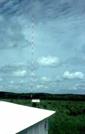
A photo of the Purple Slave station's antenna and coil house at Abeokuta taken while standing on the bulk diesel fuel tank. All the Masts in the Nigerian Chain were 100 metres tall and made by BICC and comprised of three 10 ft sectional sides bolted together to create a triangular section. 30 or so of these sections where used for each mast. The Guys each contained large tension insulators - made by Austin Insulator of Canada - a company within the Decca Group. The Guys also provided capacity loading for the mast.

A view of the Master Station at Ikorodu from the mast. The radial trenches are easily visible. The distance from the main building to the mast was approximately 150 metres. About 35 radials of stranded bare copper wire were used for each antenna and each radial was approximately 150 metres long.
The tower which can be seen was for a microwave dish for a remote link to a monitoring station at Agbowa about 7 km away. The microwave link comprised of a Farinon (SR-9000?) microwave transmitter at Agbowa and a correspoding receiver at Ikorodu. The antennas were Andrews “GridPak” antenna and the coaxial cable Andrews LDF5-50. Although called a microwave link, operation was in the 800MHz band.

Last update 26/8/2009